
Knife sharpener

a sharpener and blade technology, applied in the field of sharpeners, can solve the problems of resilient flexible fingers, physical damage or distortion, hand injury, etc., and achieve the effects of preventing damage to the environment, enhancing protection, and protecting from deterioration, damage or abus

Active Publication Date: 2007-07-19
FUERITECHNICS GROUP
View PDF19 Cites 16 Cited by
  • Summary
  • Abstract
  • Description
  • Claims
  • Application Information

AI Technical Summary

Benefits of technology

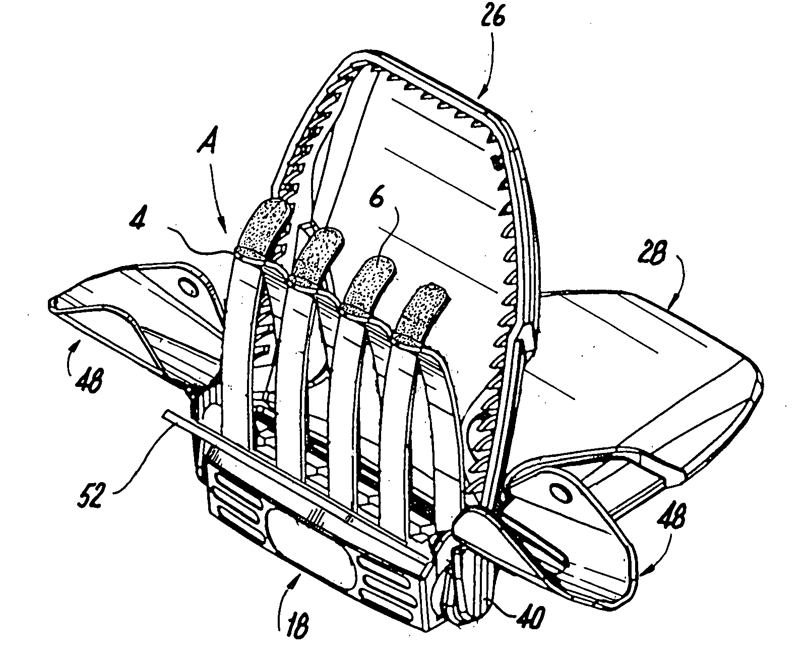
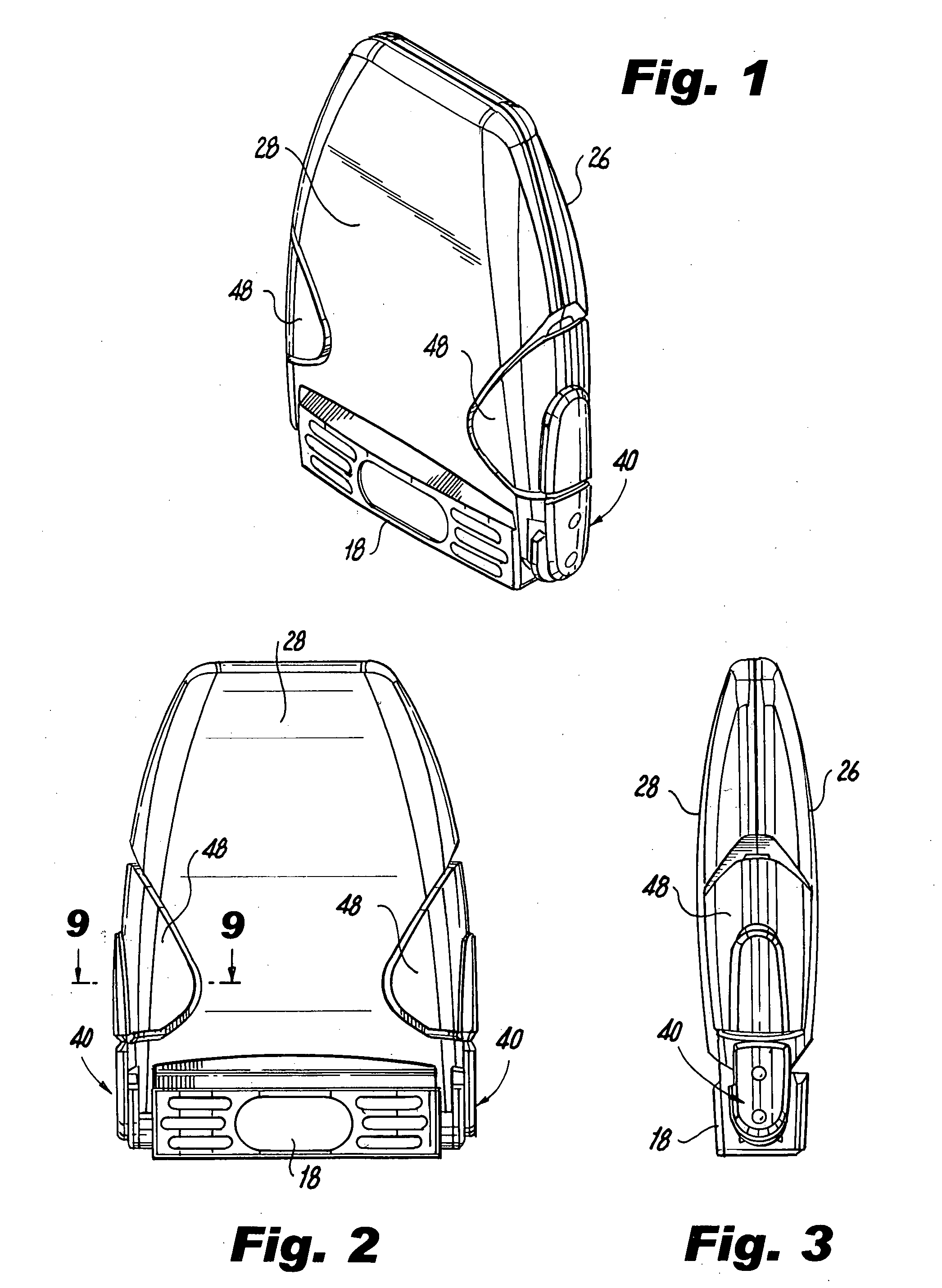
[0003] The object of the present invention is to provide a knife sharpening device preferably but not exclusively of the type involving pairs of overlapping, resiliently flexible abrasive fingers or strips, in which the knife-sharpening device is protected from deterioration, damage or abuse while being stored, in which the sharpening units are housed to prevent damage to the environment, and which provides enhanced protection to the hand of the user when the sharpener is to be operatively employed. The arrangement of parts which accomplishes those objectives are particularly adapted for use with a knife sharpener with resiliently flexible abrasive fingers or strips of the aforementioned U.S. Pat. No. 6,769,327, but is not necessarily limited thereto.
[0005] The parts of the device are readily manufactured and assembled with a minimum of precision required, with the wing-like shield locking means, when assembled with the other parts, providing the structure for articulately mounting the shields.

Problems solved by technology

The proximity of the knife, as it is drawn through the sharpening device, to the user's hand engaged in holding the device stationary on a support surface presents significant danger of injury to that hand if the knife is not manipulated in an entirely correct fashion, and hence it is highly desirable to provide the device with some means for protecting the user's holding hand.
Sharpeners of that type have proved to be exceptionally effective, but those resiliently flexible fingers, if exposed to the vicissitudes of handling and storage, are susceptible to physical damage or distortion.
Moreover, it has been found that the conventional hand-guard, usually only co-extensive with the abrasive finger assembly, does not provide adequate protection to the user's hand, particularly the thumb-portion of that hand.

Method used


Image

  • Knife sharpener
  • Knife sharpener
  • Knife sharpener

Examples


Embodiment Construction

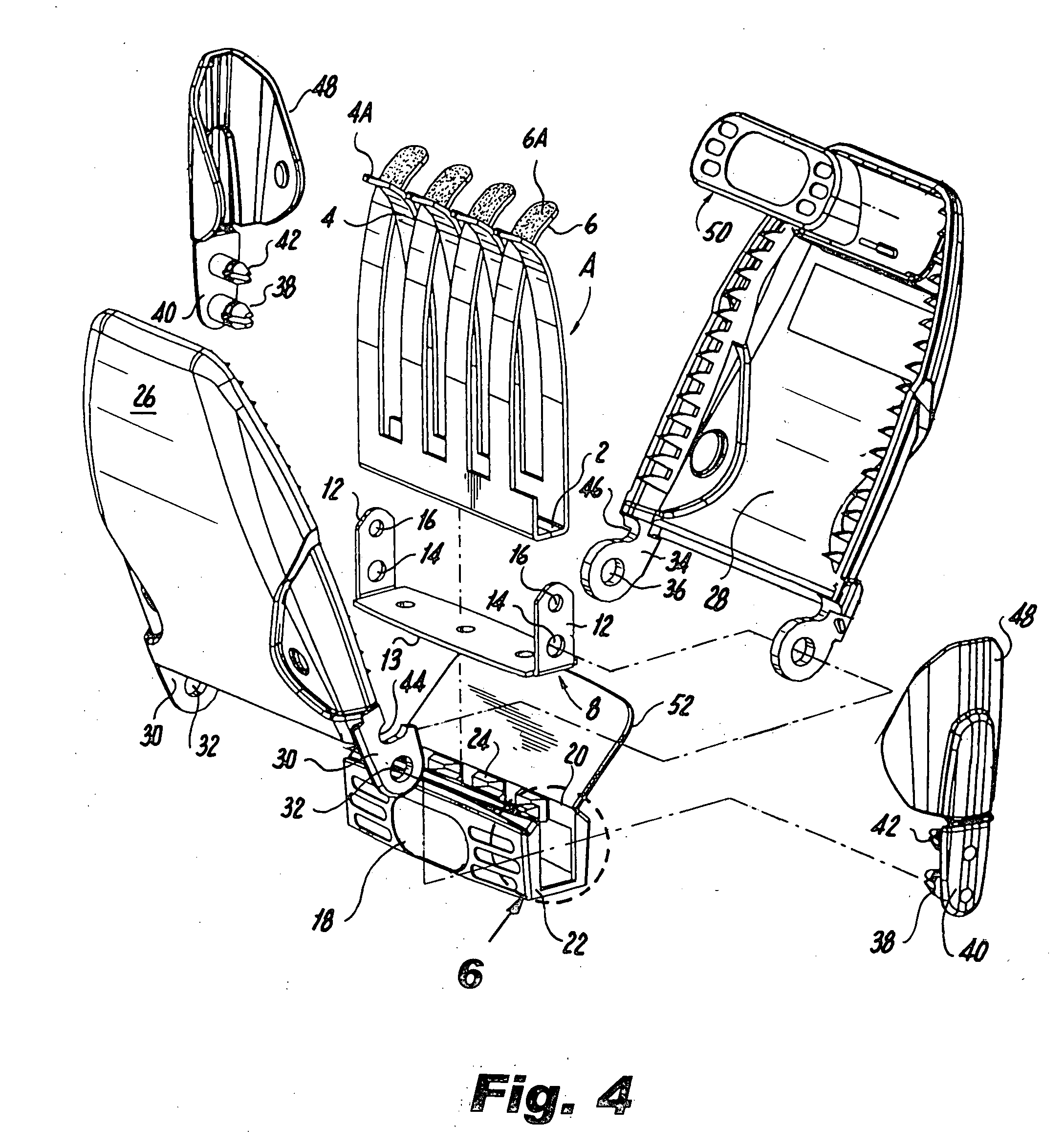
[0019] The knife sharpener device per se may be of the general type shown in U.S. Pat. No. 6,769,327. In its specific form here it is of the form of a finger assembly generally designated A, which comprises an elongated narrow bottom wall 2 from which resilient staggered sets of curved fingers 4 and 6 respectively extend upwardly, the fingers 4 at their upper extremities entering into the spaces between the fingers 6 and vice versa, the outwardly facing surfaces 4A and 6A of the fingers 4 and 6 being appropriately abrasive in nature, all as described in the aforementioned '327 patent. The finger assembly A is mounted on a base generally designated 8 comprising an elongated bottom wall 10 and upstanding side walls 12, the latter being provided with two sets of matching apertures 14 and 16 respectively. Both the finger assembly 2, 46 and the base 8 may be formed of metal and finger assembly A may be secured to the base 8 in any appropriate manner, as by spot welding.

[0020] The assemb...


PUM


Abstract

A knife sharpener comprising a sharpening device preferably of the type involving upwardly extending pairs of overlapping, resiliently flexible fingers or strips forming opposed abrasive sharpening faces, provided with a pair of shields respectively operative between closed positions in which they cover and protecting the sharpening device and open positions in which they respectively provide a handhold for the device and protect the hand of the user when it is on the handhold, and preferably provided with locking means moveable between a first position engaging said shields and retaining them in said closed position and a second position releasing said shields from their closed positions and extending out from said assembly to provide protection for the hand of the user.

Description

BACKGROUND OF THE INVENTION [0001] Many devices have been proposed for sharpening knives. One type of such device, suitable for both professional and home use, includes a structure through and across which a knife may be drawn, the device then acting on the cutting edge of the device to enhance the sharpness of that edge. Such sharpeners, when not secured to some external support, must be held in place on a horizontal support such as a table by one hand of the user, the other hand of the user manipulating the knife. The proximity of the knife, as it is drawn through the sharpening device, to the user's hand engaged in holding the device stationary on a support surface presents significant danger of injury to that hand if the knife is not manipulated in an entirely correct fashion, and hence it is highly desirable to provide the device with some means for protecting the user's holding hand. [0002] One particularly effective sharpening device is that shown in the inventor's prior U.S....

Claims


Application Information

Patent Timeline
Patent Type & Authority Applications(United States)
IPC IPC(8): B24D15/00
CPCB24D15/081
Inventor HENRY, MARK JAMES
Owner FUERITECHNICS GROUP
Learn More