Power-on error detection system and method

a technology of error detection system and power-on, applied in error detection/correction, instruments, computing, etc., can solve the problems of only being suitable for finished products or electronic devices, poor design of hardware circuits of motherboards, incorrect configuration of motherboard components, etc., to facilitate design and debugging processes, increase product efficiency, and facilitate debugging speed

Inactive Publication Date: 2007-07-19
INVENTEC CORP
View PDF2 Cites 20 Cited by
  • Summary
  • Abstract
  • Description
  • Claims
  • Application Information

AI Technical Summary

Benefits of technology

[0013] In another embodiment, the power-on error detection method according to the present invention further includes a storage unit for storing operational parameters produced during operation of the electronic device, and a second warning signal output command is stored in a segment of the BIOS program used to complete accessing the operational parameters of the storage unit, the second warning signal output command driving the signal outputting unit to output a second warning signal if the electronic device successfully accesses the operational parameters of the storage unit according to the BIOS program after the electronic device is turned on and runs a period of time. Thus, designers or debugging staff can timely know that configuration of the storage unit is correct according to the second warning signal.
[0014] As described above, a power-on error detection system and

Problems solved by technology

According to this method, after an electronic device is turned on while before the monitor of the electronic device begins to run, if error occurs in any one of components of the electronic device such as a BIOS, a memory or a display card, a LED (light-emitting diode) installed on a case of the electronic device flickers at different frequencies or displays different colors corresponding to different component damages or configuration errors of the electronic device.
However, the above method is only suitable for finished products or electronic devices having an error detection apparatus installed thereon.
The reason for errors can be poor design of hardware circuits of the motherboard, incorrect configuration of components of the motherboard, incorrect program codes in the BIOS program or the like.
If the program codes can not be loaded into the memory beca

Method used


Image

  • Power-on error detection system and method
  • Power-on error detection system and method
  • Power-on error detection system and method

Examples


Embodiment Construction

[0017] The following illustrative embodiments are provided to illustrate the disclosure of the present invention, these and other advantages and effects can be apparent to those skilled in the art after reading the disclosure of this specification. The present invention can also be performed or applied by other different embodiments. The details of the specification may be on the basis of different points and applications, and numerous modifications and variations can be devised without departing from the spirit of the present invention.

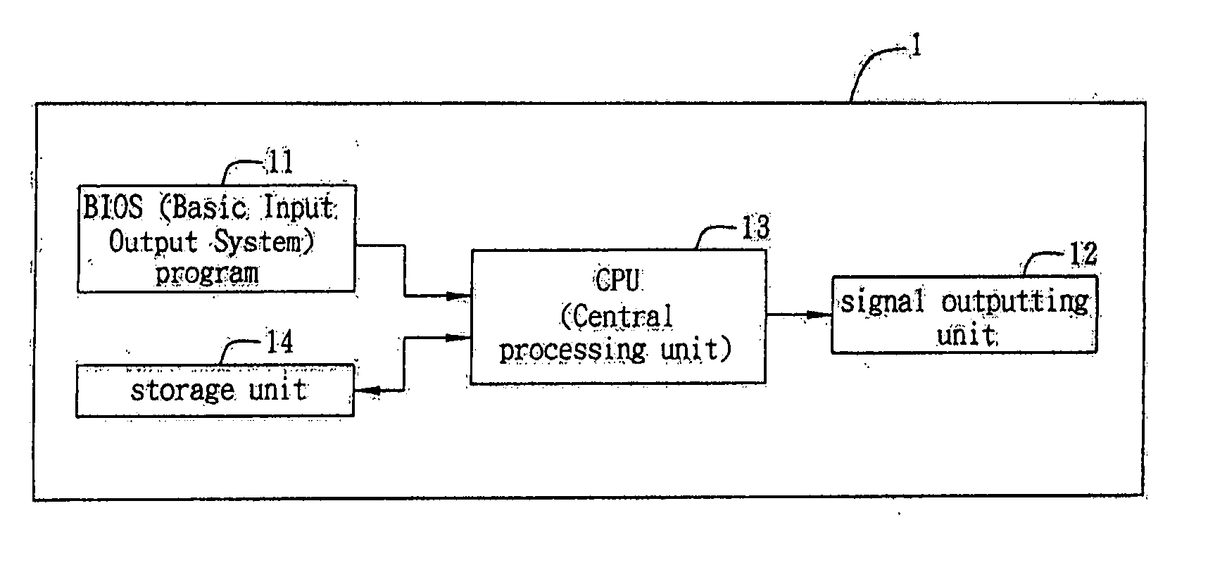
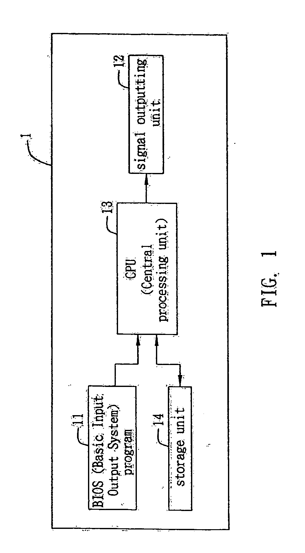
[0018]FIG. 1 is a schematic block diagram of a basic structure of a power-on error detection system according to the present invention. In the present embodiment, the power-on error detection system can be applied in an electronic device having a motherboard, wherein the electronic device can be such as a desktop computer, a notebook computer, a server, a PDA (Personal Digital Assistant), a mobile telephone and the like. As shown in FIG. 1, the powe...


PUM


Abstract

A power-on error detection system and method applicable in an electronic device having a motherboard is proposed, wherein the motherboard is provided with a memory for storing a BIOS program and a signal outputting unit. The power-on error detection system and method are used to indicate an operation state of the electronic device while the electronic device reads the BIOS program at power-on and performs a POST (Power-on self-test) process. A first warning signal output command is set in the a segment of the BIOS program. The first warning signal output command drives the signal outputting unit to output a first warning signal after the electronic device is turned on and executes the POST process according to the BIOS program stored in the memory.

Description

BACKGROUND OF THE INVENTION [0001] 1. Field of the Invention [0002] The present invention relates generally to a power-on error detection system and method, and more particularly to a power-on error detection system and method which detect whether components of an electronic device operate normally through a BIOS (Basic Input Output System) program. [0003] 2. Description of Related Art [0004] Currently, for an electronic device, there are many kinds of error detection methods, and one of the most common methods is to sound a warning signal in the event that error occurs in an electronic device. [0005] The above method is further improved by Taiwan Patent Publication No. 512275, which proposes a method for detecting and displaying errors of an electronic component. According to this method, after an electronic device is turned on while before the monitor of the electronic device begins to run, if error occurs in any one of components of the electronic device such as a BIOS, a memory ...

Claims


Application Information

Patent Timeline
IPC IPC(8): G06F11/00
CPCG06F11/2284
Inventor WANG, CHIEN-CHIH
Owner INVENTEC CORP
Why Eureka
Try Eureka