Fibre coating method and apparatus

a technology of fibre coating and apparatus, applied in the direction of coating, chemical vapor deposition coating, fibre mechanical structure, etc., can solve the problems of difficult to effectively rebuild the apparatus without effectively adjusting the operating properties of the apparatus, the inlet and outlet of the fibre can become blocked, and the throughput speed of the fibre is limited

Inactive Publication Date: 2007-07-26
BRITISH TELECOMM PLC
View PDF10 Cites 5 Cited by
  • Summary
  • Abstract
  • Description
  • Claims
  • Application Information

AI Technical Summary

Problems solved by technology

A problem with this known arrangement is that the fibre inlet and outlet can become blocked with particles requiring downtime to clear the blockage.
This can be a particular problem when the microspheres are electrostatically charged as they are attracted to other surfaces than the fibre unit surface.
A problem with this arrangement is that it, is difficult to adjust the operating properties of it without effectively rebuilding the apparatus as its operation is highly dependent on the configuration of the through passage.
A further problem with known arrangements is that the throughput speed for coating the fibre is limited, with the apparatus unable to reach speeds of the order of 300 m / min without severely affecting the uniformity of distribution of the embedded microspheres.
Further problems with known arrangements are that in some cases it may be difficult to ensure that there is no leakage of microspheres from known apparatus.

Method used


Image

  • Fibre coating method and apparatus
  • Fibre coating method and apparatus
  • Fibre coating method and apparatus

Examples


first embodiment

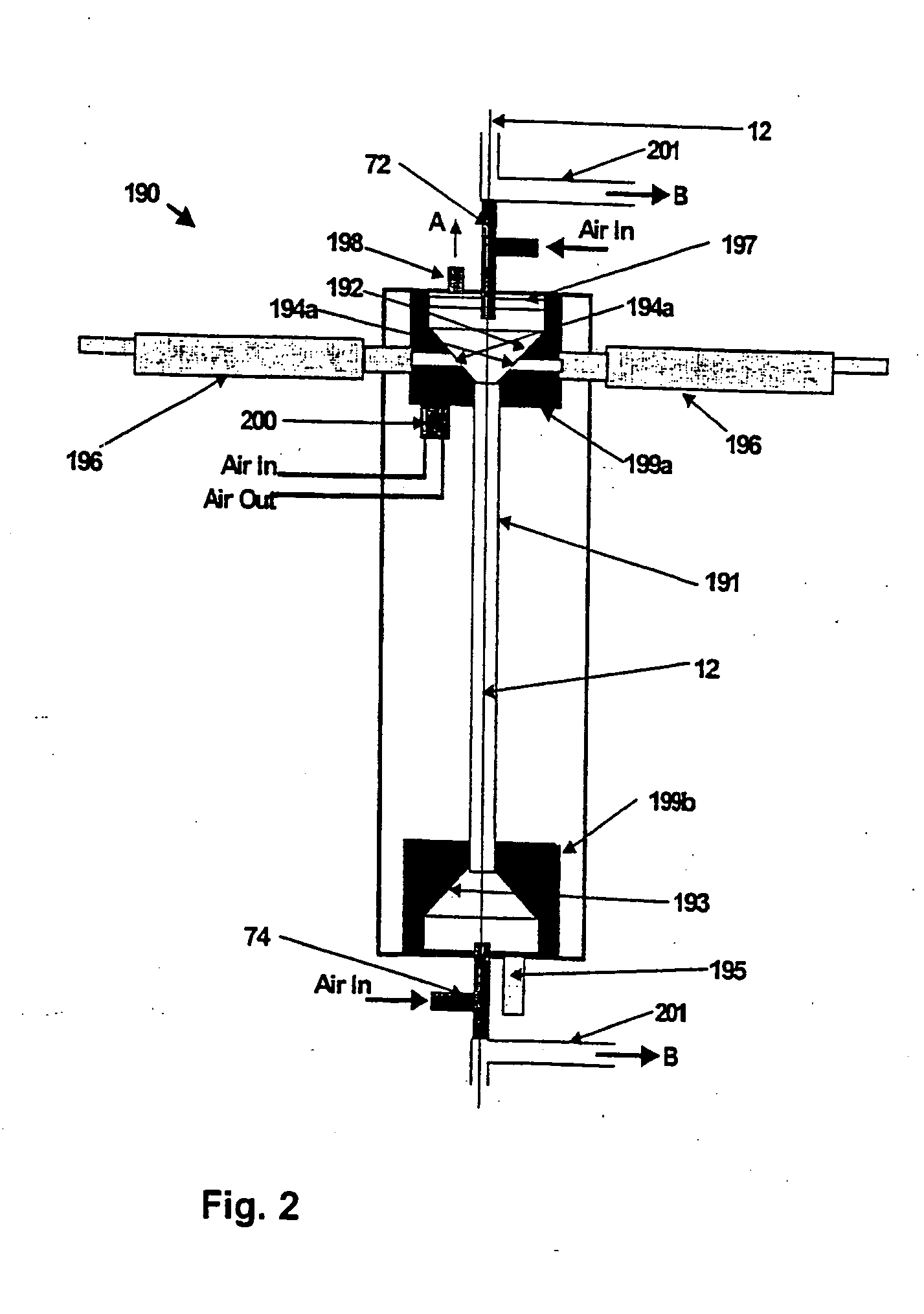
[0027] the fibre coating unit 18 is shown in FIG. 2. The uncured resin coated fibre unit 12 passes through a coating chamber 190, which comprises a generally cylindrical glass tube 191 terminating at each end in a substantially solid block (199a and 199b) which each define a chamber having a frusto-conical surface (192 and 193). The fibre unit 12 also passes through positive pressure chamber 72 located adjacent the first end 192 and positive pressure chamber 74 located adjacent the second end 193.

[0028] A mixture of air and microspheres is admitted into the coating chamber via two ducts 196 passing through block 199a and apertures 194a located in the frusto-conical surface 192. Although in the embodiment there are only two ducts and apertures, it is understood that the air and microsphere mixture may be admitted using a plurality of ducts / apertures entering either through the walls of the block 199a or alternatively directly into the tube 191 (as shown later in FIG. 3). The air and ...

second embodiment

[0036] the fibre coating unit 18 is shown in FIGS. 5-7, and comprises positive pressure chamber 301, coating chamber 302 and positive pressure chamber 303. The uncured resin coated fibre unit 12 passes through these in the direction indicated by arrow 300. An air and microsphere mixture within coating chamber 302 causes multiple microspheres to adhere to the uncured resin coating of the fibre unit, which is then cured downstream as discussed earlier.

[0037] Coating chamber 302 comprises two substantially solid blocks 304 and 305, separated by a cylindrical glass tube 191, which together define a passage through which the fibre unit 12 passes. A mixture of air and microspheres is admitted into the coating chamber 302 (in the directions indicated by arrows 308 and 309) via two inlet ducts 306 and 307 formed within upper block 304. The two ducts 306 and 307 open into an annular cavity 314 within block 304. The cavity 314 is formed concentrically around the passage through which the fibr...

third embodiment

[0046] the fibre coating unit 18 is shown in FIGS. 8-10, and comprises positive pressure chamber 301, coating chamber 802 and positive pressure chamber 303. The uncured resin coated fibre unit 12 passes through these in the direction indicated by arrow 300. An air and microsphere mixture within coating chamber 802 causes multiple microspheres to adhere to the uncured resin coating of the fibre unit, which is then cured downstream as discussed earlier.

[0047] Coating chamber 802 comprises two substantially solid blocks 804 and 305, separated by a cylindrical glass tube 191, which together define a passage through which the fibre unit 12 passes. A mixture of air and microspheres is admitted into the coating chamber 802 (in the directions indicated by arrows 308 and 309) via two inlet ducts 806 and 807 formed within upper block 804. The two ducts 806 and 807 open into an annular cavity 814 within block 804 formed concentrically around the passage through which the fibre unit will pass. ...


PUM

PropertyMeasurementUnit
diameteraaaaaaaaaa
diameteraaaaaaaaaa
speedsaaaaaaaaaa

Abstract

A fibre unit coating apparatus includes a chamber into which an uncured resin coated fibre unit is passed. Microspheres mixed with air are fed into the chamber via ducts and apertures. As a result rapid and even application of the microspheres can be achieved, and the system allows controllable application of the microspheres by varying the rate of flow of the air/microsphere mixture. Positive pressure chambers are provided to prevent the microspheres from blocking the inlet and outlet points where the fibre unit enters and leaves the chamber.

Description

CROSS REFERENCE TO RELATED APPLICATION [0001] This application is a divisional of U.S. patent application Ser. No. 10 / 513,883 filed Nov. 9, 2004 which was the national phase of PCT / GB 03 / 02011 filed May 9, 2003 and which claimed priority from GB Application No. 0210760.5 filed on May 10, 2002, the disclosure of which priority applications is incorporated herein by reference.BACKGROUND [0002] 1. Technical Field [0003] The invention relates to a fibre coating method and apparatus in particular for coating optical fibres. [0004] 2. Related Art [0005] It is known to protect optical fibres by laying them in ducts. One well-known approaching to laying the fibres in ducts comprises fibre blowing (or “blown fibre”). European patent application no. 0108590, commonly assigned herewith describes a fibre blowing technique in which the fibre is blown into a duct on a cushion of air, relying on viscous drag to advance the fibre. [0006] In order to further protect the fibres conventional resin coa...

Claims


Application Information

Patent Timeline
Patent Type & Authority Applications(United States)
IPC IPC(8): B05D1/12B05D3/00C23C16/00B05C5/00G02B6/44C03C25/12C03C25/14C03C25/143C03C25/24C03C25/47
CPCC03C25/101C03C25/143C03C25/12C03C25/47
Inventor BARKER, PHILIPFISK, CHRISTOPHERSMITH, RAYMOND
Owner BRITISH TELECOMM PLC
Why Eureka
Try Eureka