Fully-adjustable glove removal apparatus

a fully adjustable, glove technology, applied in the field of surgical glove removal, can solve the problems of difficult undesirable to attempt to remove these types of gloves without some external instrument, etc., and achieve the effect of greater options

Inactive Publication Date: 2007-07-26
KELLY TRAVIS L
View PDF7 Cites 9 Cited by
  • Summary
  • Abstract
  • Description
  • Claims
  • Application Information

AI Technical Summary

Benefits of technology

[0021] It is a further object of this invention to provide apparatus which is capable of being adjusted as to overall length allowing greater options as to the positioning of the flanges with regar...

Problems solved by technology

The removal of these type of gloves is often difficult to do, owing to the manner in which the gloves themselves provide a constricting force on all of the surface area of the wearer's hand.
In addition, it is often undesirable to attempt removal of these types of gloves without some external instrument, i...

Method used


Image

  • Fully-adjustable glove removal apparatus
  • Fully-adjustable glove removal apparatus
  • Fully-adjustable glove removal apparatus

Examples


Embodiment Construction

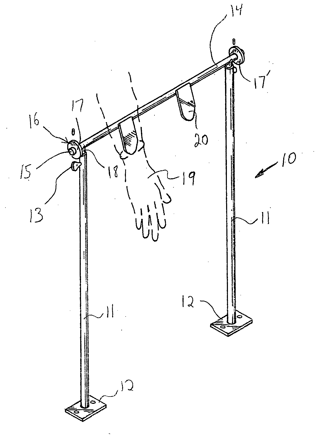
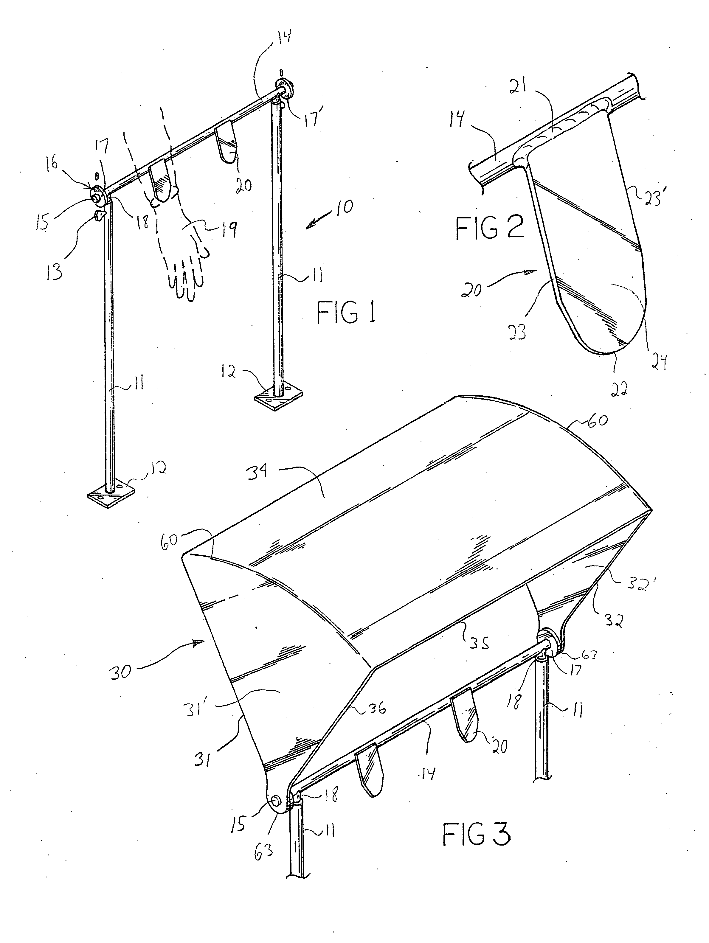
[0033] Referring now to FIG. 1 a framework 10 is provided, comprising two support legs 11, each having a bottom end which defines a means for attachment to a separate supporting surface, and a top end for supporting a crossmember 14. Said support legs 11 are generally parallel to each other and are spaced apart by a crossmember 14. Said crossmember 14 is attached to each support leg 11 along its length so that the ends 15 of the crossmember 14 protrude beyond the point where the support leg 11 is attached. In this manner, the support legs 11 and crossmember 14 define a U-shaped framework 10.

[0034] Referring now also to FIG. 2, along the length of crossmember 14, are one or more flange members 20, which are defined as generally flat sections of material having a width as defined from a first side edge 23 to a second side edge 23′, with a peripheral end 22 defining a curved or arcual shape. The flange member 20 has a relatively small thickness, with the peripheral end 22 having a thi...


PUM


Abstract

A surgical glove removal apparatus in which a crossmember supports one or more flanges that are able to be slipped between the wearer's glove and hand, so that when the hand is withdrawn, the flange peels the glove off away from the wearer. A shield is provided to prevent unwanted splatter, with the shield being adjustable virtually 360 degrees about the crossmember. The crossmember is supported by support legs that are able to be attached to virtually any surface angle, with the flanges able to be utilized with the apparatus attached to a floor surface, a table surface, a wall surface, or even an elevated or ceiling surface, allowing for complete versatility in the placement of this apparatus in a medical setting. The shield and flanges may be adjustable as to position for the user, with the height or extension of the support legs also adjustable so as to accommodate any mounting surface and make it appropriate for the mounting and use of this apparatus.

Description

BACKGROUND OF THE INVENTION [0001] Two basic concepts exist for surgical glove removal. The first concept uses vacuum pressure chambers to modify the shape and size of the gloves. Recent art has utilized improvements on this first concept. The second basic concept for surgical glove removal uses an external instrument to pull the glove away from the hand. Prior art generally is not intended for attachment to a ceiling or wall, as the present invention does. Further, shields and guards are desirous, since substances on the gloves may contain unwanted contaminants. [0002] Referring now to U.S. Pat. No. 4,002,276 (Poncy et al.), a method for putting on surgical gloves is shown. This invention typifies an early method for using vacuum chambers to put on gloves, and logically also to remove, surgical gloves. [0003] Referring now to U.S. Pat. No. 4,876,747 (Coffey et al.), a removal method for a specific type of glove is shown, in which the glove itself is equipped with a loop that is abl...

Claims


Application Information

Patent Timeline
IPC IPC(8): A47G25/90
CPCA47G25/904A61B19/04A61B2019/046A61B19/42A61B19/26A61B42/50A61B90/50A61B42/00A61B90/05
Inventor KELLY, TRAVIS L.
Owner KELLY TRAVIS L
Why Eureka
Try Eureka