Voting Machine with Secure Memory Processing

a technology of secure memory and voting machine, applied in the field of voting machine with secure memory processing, can solve the problems of software that cannot resist tampering very well, can be quite complex, and modern software tends to be error-pron

Inactive Publication Date: 2007-07-26
ORTON KEVIN R
View PDF4 Cites 9 Cited by
  • Summary
  • Abstract
  • Description
  • Claims
  • Application Information

AI Technical Summary

Problems solved by technology

Many voting machines are purely mechanical in operation, and as such are a bit archaic for modern standards.
They also are subject to mechanical and user errors that can give inaccurate results, which is undesirable.
These systems can be quite complex.
However, even modern software tends to be error prone.
Software also does not resist tampering very well, making the use of complex security and encryption algorithms necessary.
Even then, the software protection techniques are not always effective.
Neither is the certification process error free, as software can be written with “back doors”, which can not be found in normal testing.
This can lead to improper vote counts.
It can be difficul...

Method used


Image

  • Voting Machine with Secure Memory Processing
  • Voting Machine with Secure Memory Processing
  • Voting Machine with Secure Memory Processing

Examples


Embodiment Construction

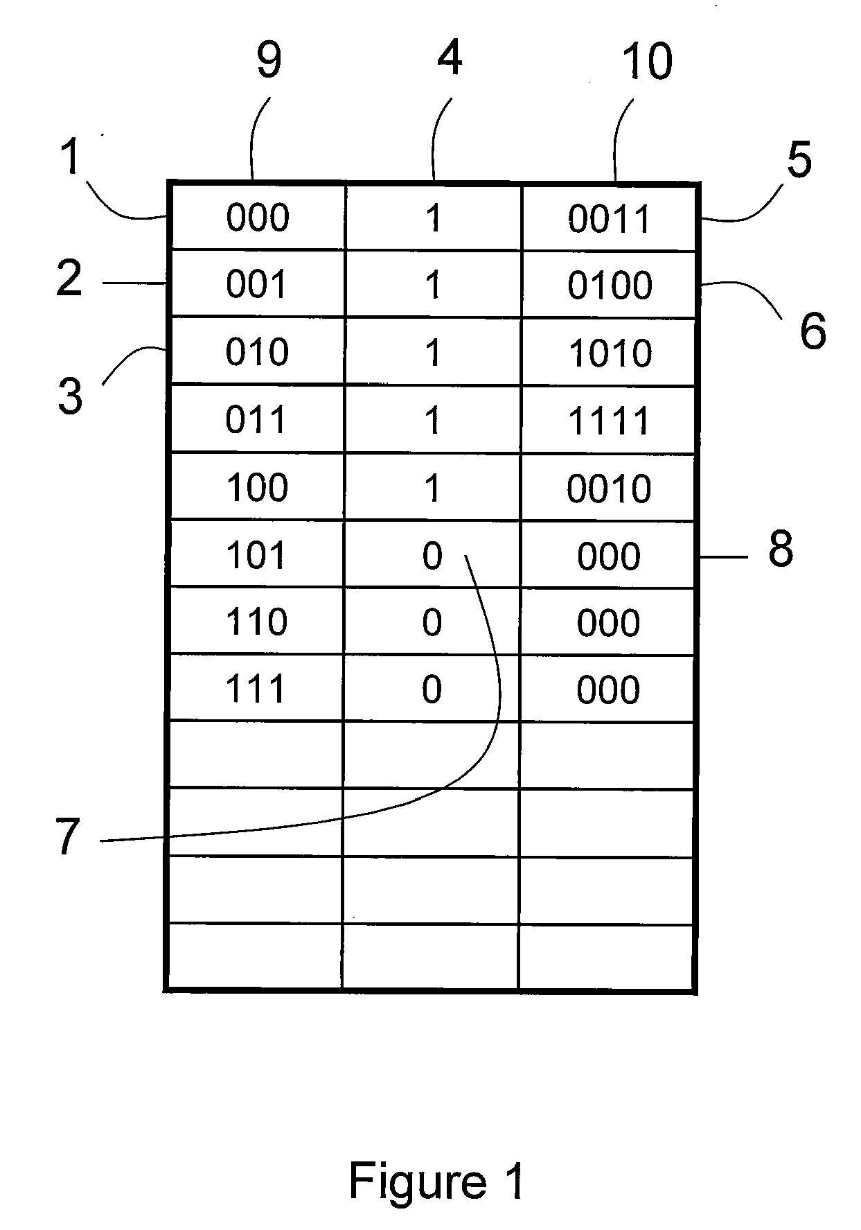
[0012]FIG. 1 shows how the voting memory is laid out in one preferred embodiment. FIG. 1 depicts the memory laid out in a row-column format. Column (9) depicts the address for each memory location. The address may be sequentially numbered in binary format, and are generally selected by a memory counter that is part of the circuitry of the chip. In rows 1, 2, and 3, (1) (2) (3), the memory counter address starts at zero and increases from there.

[0013]Column (4) contains a write-protect bit. This bit is blank initially. Column (10) contains vote data. Column (10) is typically much wider than shown, and contains vote data for all initiatives of one ballot to be cast. It may also contain check sum information or other information to help insure proper tabulation.

[0014]When a new ballot is to be cast, the memory counter selects the next available incremental address within the memory array. For example, if this is the second ballot to be cast since the chip was initialized, the memory co...


PUM


Abstract

An integrated voting system includes a memory element configured with multiple lock bits. Lock bits are arranged according to vote records, thereby allowing each individual vote cast to be recorded securely, providing a tamper-resistant record of the vote count. The system forms a complete, integrated, secure voting system that can be re-used on different elections without requiring any updates, changes, or other maintenance.

Description

CROSS-REFERENCE TO RELATED APPLICATIONS[0001]This application claims priority to and incorporates by reference U.S. provisional patent application Ser. No. 60 / 762,192, filed Jan. 24, 2006, and U.S. provisional patent application Ser. No. 60 / 762,357, filed Jan. 26, 2006.BACKGROUND OF THE INVENTION[0002]Voting machines are an important requirement for a democratic society. They help provide accurate and efficient voting. Many voting machines are purely mechanical in operation, and as such are a bit archaic for modern standards. They also are subject to mechanical and user errors that can give inaccurate results, which is undesirable.[0003]Other more modern systems are electronic. They often feature display screens, custom software, and many user controls. These systems can be quite complex. These systems are software controlled. However, even modern software tends to be error prone. Software also does not resist tampering very well, making the use of complex security and encryption al...

Claims


Application Information

Patent Timeline
IPC IPC(8): G07C13/00
CPCG07C13/00
Inventor ORTON, KEVIN R.
Owner ORTON KEVIN R
Why Eureka
Try Eureka