Vehicle surroundings monitoring apparatus
a technology for monitoring apparatus and vehicle surroundings, applied in scene recognition, television systems, instruments, etc., can solve problems such as cost increase, and achieve the effects of reducing apparatus cost, reducing relative speed, and shortening vehicle arrival tim
- Summary
- Abstract
- Description
- Claims
- Application Information
AI Technical Summary
Benefits of technology
Problems solved by technology
Method used
Image
Examples
first embodiment
[0051]The following describes a method of estimating the time to arrival at the vehicle 10 of the object monitored by the image processing unit 1 according to the first embodiment of the present invention with reference to FIG. 3. In FIG. 3, Im1 designates an image taken by the infrared camera 2 at an imaging time point t11 and Im2 designates an image taken by the infrared camera 2 at a time point t10 which is a time interval dT (corresponding to the predetermined time interval according to the present invention) later than the time point t11.
[0052]Im1 includes an image portion 31 of a pedestrian as a monitored object and Im2 includes an image portion 30 of the identical pedestrian. Referring to FIG. 3, there is shown a situation in which the pedestrian is walking toward the vehicle 10. The width w10 of the image portion 30 of the pedestrian in Im2 is greater than the width w11 of the image portion 31 of the pedestrian in Im1 since the pedestrian comes closer to the vehicle at the i...
second embodiment
[0055]Subsequently, an execution procedure for a contact determination process between the monitored object and the vehicle 10 performed by the image processing unit 1 according to a second embodiment of the present invention will be described with reference to a flowchart shown in FIG. 4. The image processing unit 1 inputs an image signal, which is output from the infrared camera 2 in step 1, first, and then captures a grayscale image converted from the image signal to digital tone (luminance) data into the image memory in step 2. In the next step 3, the image processing unit 1 obtains a binary image by binarization in which a value of “1” (white) is set if the luminance value of a pixel is a predetermined threshold value or greater and a value of “0” (black) is set otherwise for each pixel of the grayscale image.
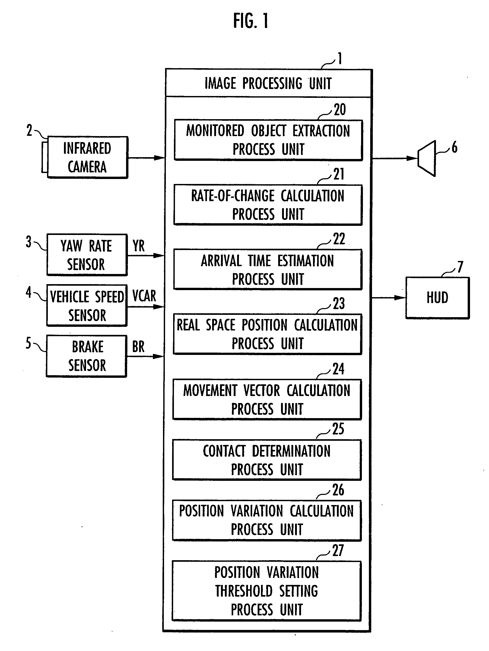
[0056]The subsequent steps 4 to 6 correspond to processes performed by the monitored object extraction process unit 20. The monitored object extraction process unit 20 cal...
third embodiment
[0085]The following describes an execution procedure for the contact determination process between the monitored object and the vehicle 10 performed by the image processing unit 1 according to a third embodiment of the present invention with reference to a flowchart shown in FIG. 8. Processing of step 30 to step 37 in FIG. 8 is similar to the above processing of step 1 to step 8 in FIG. 4. In step 37, the rate-of-change calculation process unit 21 calculates the rate of change Rate.
[0086]The next step 38 is performed by the position variation calculation process unit 26. The position variation calculation process unit 26 calculates the position variations Δx (horizontal direction) and Δy (vertical direction) of the image portion of the identical monitored object in the plurality of images used in the tracking at time intervals of step 37. Processing of the next step 39 to step 40 and step 50 is performed by the contact determination process unit 25. The contact determination process...
PUM
 Abstract
Description
Claims
Application Information
 - R&D
- Intellectual Property
- Life Sciences
- Materials
- Tech Scout
- Unparalleled Data Quality
- Higher Quality Content
- 60% Fewer Hallucinations
Browse by: Latest US Patents, China's latest patents, Technical Efficacy Thesaurus, Application Domain, Technology Topic, Popular Technical Reports.
© 2025 PatSnap. All rights reserved.Legal|Privacy policy|Modern Slavery Act Transparency Statement|Sitemap|About US| Contact US: help@patsnap.com


