Power supply device for a LCD backlight panel

Inactive Publication Date: 2007-07-26
NIKO SEMICON
View PDF1 Cites 10 Cited by
  • Summary
  • Abstract
  • Description
  • Claims
  • Application Information

AI Technical Summary

Benefits of technology

[0010] The adjusting and enabling control device produces an enabling signal to the switching electronic ballast circuit according to a low frequency signal for adjusting pulse wave width. The signal i

Problems solved by technology

The energy conversion of the conventional method has to be carried out twice, which would result energy loss twice and therefore an overall conversion efficiency is reduced.
Such a large range of

Method used


Image

  • Power supply device for a LCD backlight panel
  • Power supply device for a LCD backlight panel
  • Power supply device for a LCD backlight panel

Examples


Embodiment Construction

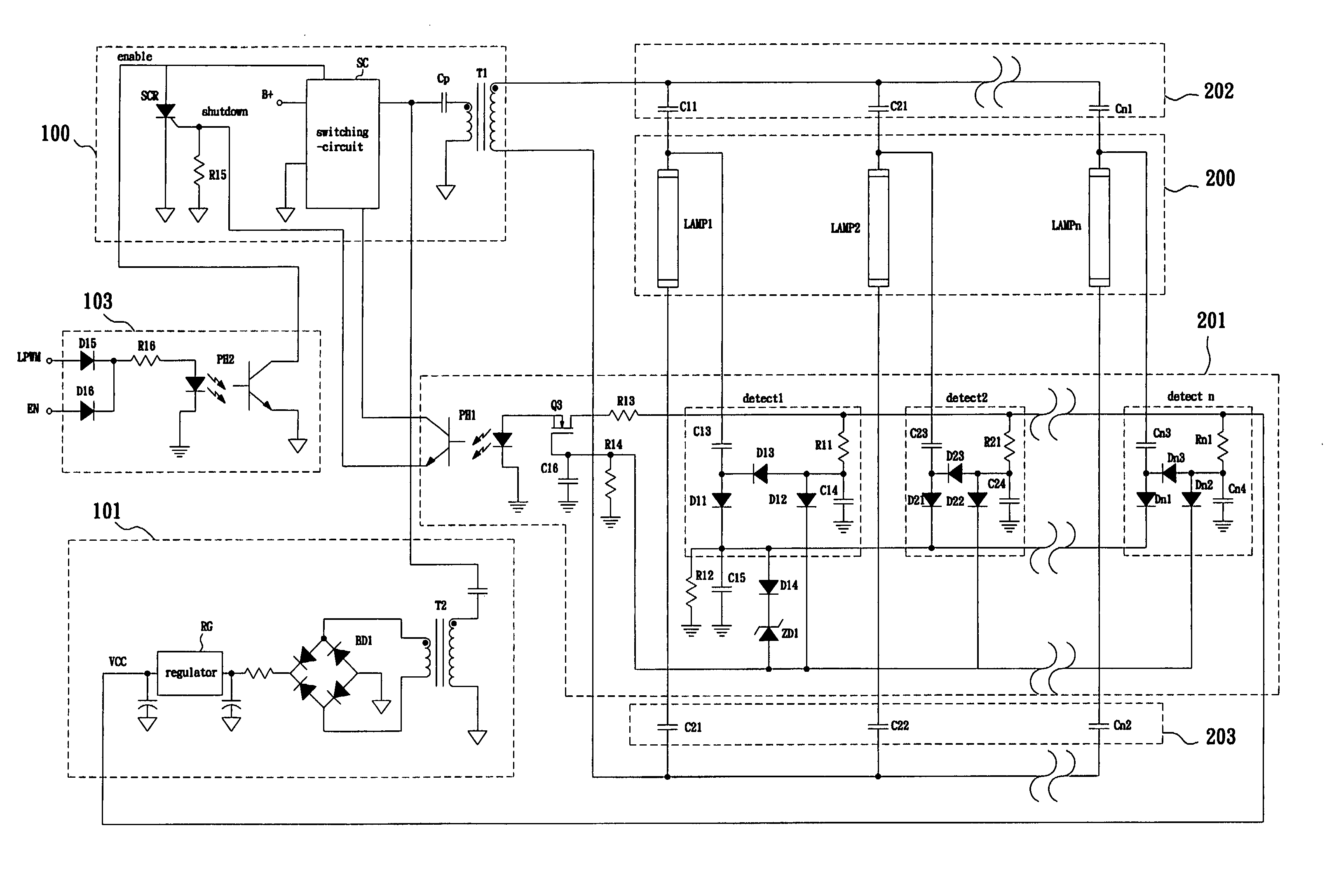
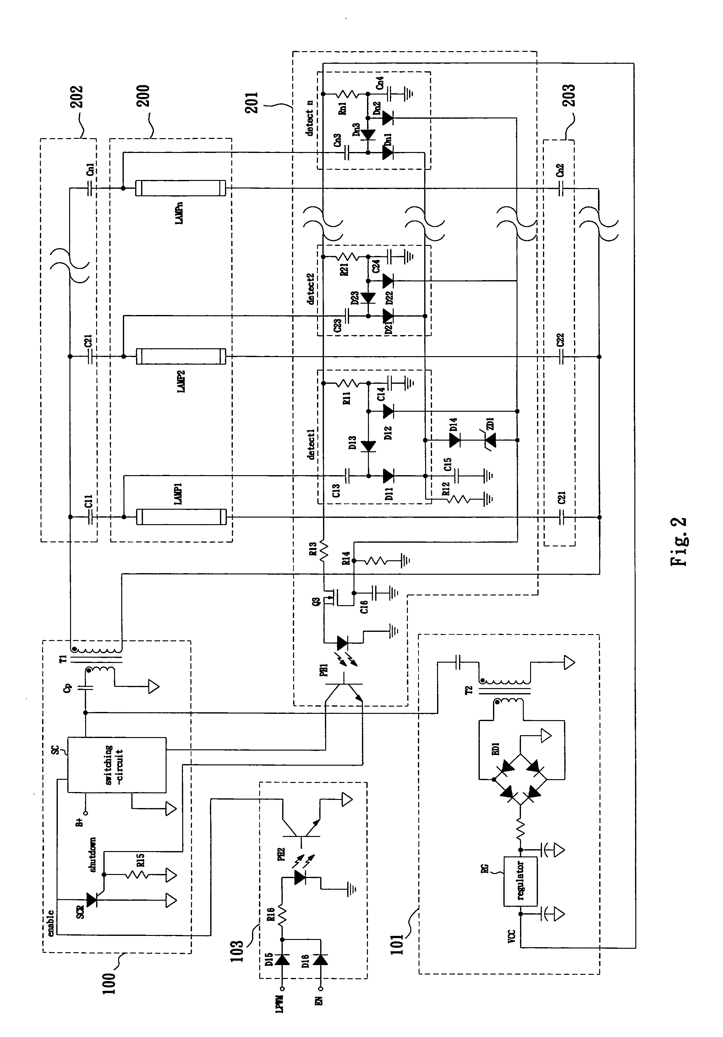
[0018]FIG. 2 shows a schematic view of an improved power supply circuit of a LCD panel in accordance with a preferred example of the present invention. The power supply circuit of a LCD panel comprises a switching electronic ballast circuit 100, wherein switch circuit SC of half bridge or full bridge topology is provided on the switching electronic ballast circuit 100 and through the resonant circuit to produce alternate sine wave voltage of high frequency. A transformer T1 will convert the alternate sine wave voltage to the secondary of the transformer T1 to output the alternate sine wave voltage with high frequency required by CCFL, LAMP1-LAMPn in order to supply the energy to the CCFL 200. The CCFL abnormal detective circuit 201 detects abnormality of every CCFL, LAMP1-LAMPn.

[0019] An impedance matching device at positive end 202 is utilized to balance current, and an impedance matching device at negative end 203 can be provided on the circuit to balance current in order to bala...


PUM


Abstract

The present invention provides an improved power supply circuit for a backlight control of the LCD panel, capable of initiating a plurality of CCFL. The electrical lighting device comprises an switching electronic ballast circuit, a CCFL abnormal detective circuit, an impedance matching device at positive end of balancing current, an adjusting and enabling control device and an auxiliary power source circuit. The circuit of the electrical lighting device is designed to protect the circuit from abnormal conditions such as short-circuit occurred on a seal cover. The impedance matching device at positive end is provided in between negative ends of some cold cathode fluorescence lamps and an anode of secondary winding of the transformer to balance the CCFL current. Detective units and signals are provided to detect anode voltage in order to determine abnormality in the circuit.

Description

FIELD OF INVENTION [0001] The present invention relates to a power supply device for a backlight panel of liquid crystal display (LCD). More particularly, the present invention relates to a power supply with a design of current balancing and functions for testing the abnormalities of cold cathode fluorescence lamps (CCFL) and adjusting the intensity thereof. Description of the Related Art [0002] In the backlight power supply of a liquid crystal display (LCD) a high frequency sine wave is utilized as the power source to provide the energy needed for driving cold cathode fluorescence lamps (CCFL). Thus, the conventional method utilizes normally an inverter circuit to transform the direct current (DC) into the alternate current (AC) in order to achieve the energy transfer. Those conventional inverter circuits are categorized into half-bridge inverter circuits, full-bridge inverter circuits and push-pull inverter circuits according to the circuit topologies. [0003] Further, the alternat...

Claims


Application Information

Patent Timeline
IPC IPC(8): G09G3/36
CPCH05B41/2822
Inventor HSU, DA-JING
Owner NIKO SEMICON
Why Eureka
Try Eureka