Method for creation of architectural space objects

a technology for creating space objects and buildings, applied in the field of computer-aided design software, can solve problems such as laborious and error-prone process of maintaining area-related information, and contribute to the total area of the room

Active Publication Date: 2007-07-26
AUTODESK INC
View PDF9 Cites 46 Cited by
  • Summary
  • Abstract
  • Description
  • Claims
  • Application Information

AI Technical Summary

Benefits of technology

[0012] Once generated, the space object may provide users with calculations such as the area or volume of the space represented by the space object. For example, the gross, net, and useable areas may be calculated as these areas are defined by established standards (e.g., the BOMA or SIS standards), based on styles associated with the CAD model or elements thereof, and / or based on user input. Further, in response to user commands, the CAD application may be configured to generate space objects automatically by detecting spaces in the CAD model bounded by AEC elements such as walls, ceilings and floors, and / or by detecting regions bounded by more simple drawing elements such as lines and arcs without the user having to specify the boundary elements for a space object manually.

Problems solved by technology

For example, standards established by the Swedish Institute for Standards (SIS) specify that areas in a room with a ceiling height below 1.9 meters do not fully contribute to the total area of the room.
Thus, unless the space values are recalculated whenever the CAD drawing is modified, the calculations may become incorrect and obsolete.
This makes the process of maintaining area-related information tedious and error-prone.
Moreover, the definition of space boundaries in “open” floor plans may be ambiguous; without AEC elements to define a boundary between two adjoining spaces, the CAD application may be unable to perform space calculations correctly.

Method used


Image

  • Method for creation of architectural space objects
  • Method for creation of architectural space objects
  • Method for creation of architectural space objects

Examples


Embodiment Construction

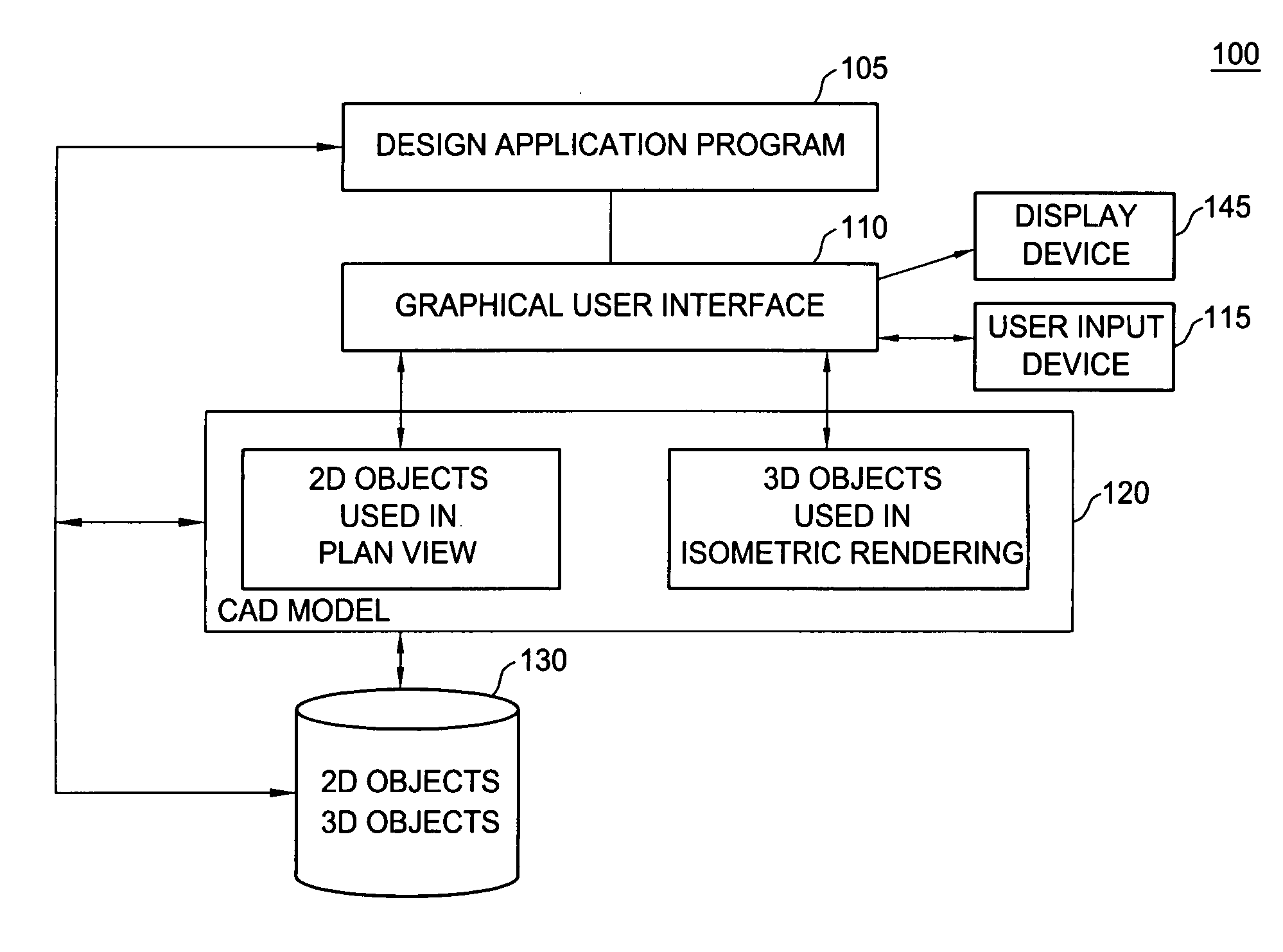
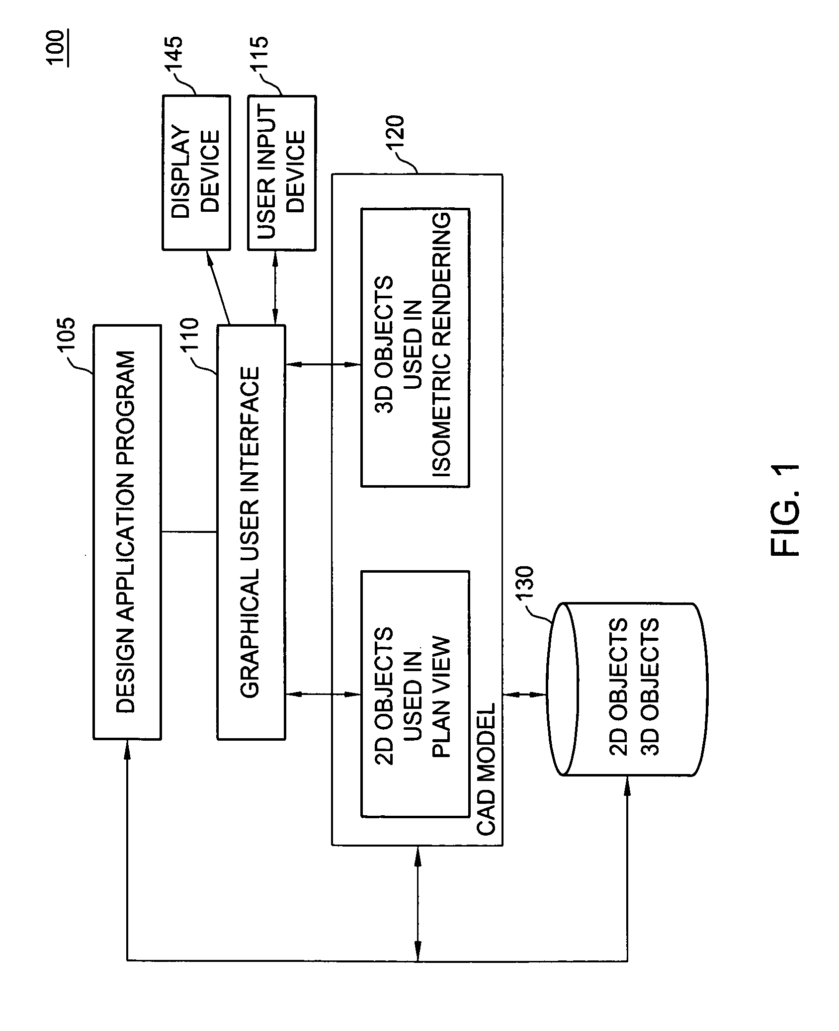
[0028]FIG. 1 is a block diagram illustrating a computer-aided design (CAD) application environment 100, according to one embodiment of the invention. In one embodiment, the components provided by environment 100 may include computer software applications executing on a computer system such as a desktop computer, server, laptop computer, tablet computer, and the like. However, the components illustrated in environment 100 are not limited to any particular computing environment, programming language, or computer hardware and / or software combination, and embodiments of the invention may be adapted to take advantage of new computing systems as they become available. Additionally, the components illustrated in FIG. 1 may be present on multiple systems communicating over computer networks including local area networks or wide area networks such as the Internet. For example, a graphical user interface 110 (GUI interface) may be a software application executing on a client computer communic...


PUM


Abstract

Embodiments of the invention allow users to generate and maintain space objects in a computer-aided design model representing regions bounded by a set of drawing elements included in the model. The space object contains the geometry of such a bounded region and may be used to calculate values such as area and volume associated with the region. Additionally, each space object may be associated with the set of drawing elements bounding the region represented by the space object such that any changes to one of the associated bounding elements causes the geometry of the space object to be updated automatically to reflect these changes. Areas and volumes calculated from the space object geometry may conform to established standards regarding the calculation of gross, net and useable areas of a building or other structure.

Description

BACKGROUND OF THE INVENTION [0001] 1. Field of the Invention [0002] The present invention is generally directed to computer-aided (CAD) design software. More specifically, the present invention is directed to a CAD application configured to create and manipulate objects representing open space areas or volumes in a drawing or model generated using a CAD application. [0003] 2. Description of the Related Art [0004] The term computer-aided design (CAD) generally refers to a broad variety of computer-based tools used by architects, engineers, and other construction and design professionals. CAD applications may be used to construct computer models representing virtually any real-world construct. Commonly, CAD applications are used to generate computer models of construction projects, e.g., residential homes, office buildings, roadways, bridges, etc. A CAD application may provide users with a variety of two-dimensional (2D) and three-dimensional (3D) views related to a particular design ...

Claims


Application Information

Patent Timeline
Patent Type & Authority Applications(United States)
IPC IPC(8): G06T17/00
CPCG06T19/00G06F17/5004G06T2210/04G06F30/13
Inventor MCARDLE, PAULARVIN, SCOTTWU, QIONGOSCARSON, ANNA
Owner AUTODESK INC
Why Eureka
Try Eureka