
Ceramic matrix laminates

a technology of ceramic matrix and laminate, applied in the field of ceramic matrix laminate, can solve the problems of forming a high-quality bond, material failure in shear, and not supporting the full load from the face pla

Active Publication Date: 2007-07-26
RTX CORP
View PDF9 Cites 17 Cited by
  • Summary
  • Abstract
  • Description
  • Claims
  • Application Information

AI Technical Summary

Benefits of technology

"The patent describes methods and systems for making a ceramic matrix laminate (CML) using a ceramic felt core between two ceramic matrix composite (CMC) face plates. The methods can involve in-situ fabrication of the core and increasing the density of the CMC face plates simultaneously or infiltrating pre-formed cores into the CMC face plates. The ceramic matrix laminate (CML) made using these methods has a high quality and can be used in various applications such as aerospace structures."

Problems solved by technology

One problem with the fabrication of a sandwich type structure is forming a high-quality bond between the face plates and the core material.
If the bond between the face plates is weak, the material will fail in shear and not support the full load from the face plates.
In sandwich structures employed for high-temperature applications, the use of adhesives to bond the face plates to the core material may lead to debonding of the face plates from the core due to different coefficients of thermal expansion among the materials.
In addition, most high temperature glues shrink, outgas, and crack when heated to the application temperature.
This ultimately results in a weak or failed bond.
Although there are various systems and methods of constructing ceramic matrix laminates, such systems and methods are not completely satisfactory.

Method used


Image

  • Ceramic matrix laminates
  • Ceramic matrix laminates
  • Ceramic matrix laminates

Examples


Embodiment Construction

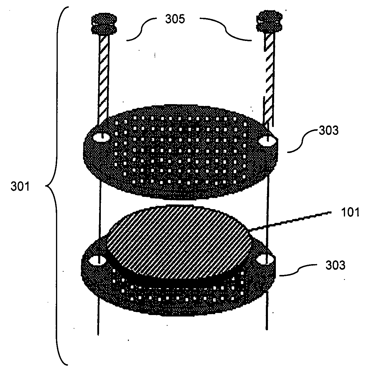
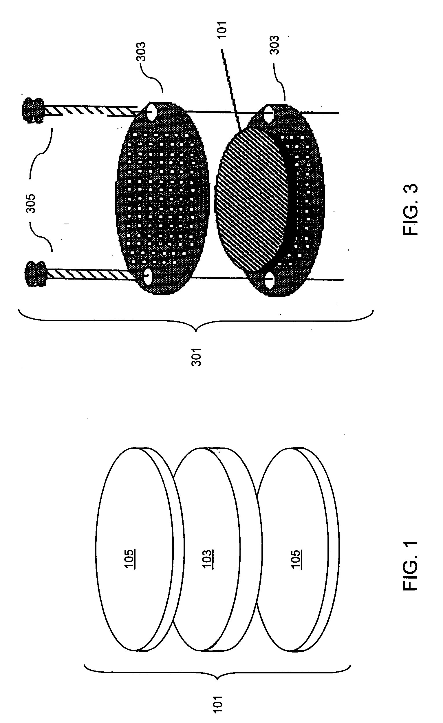
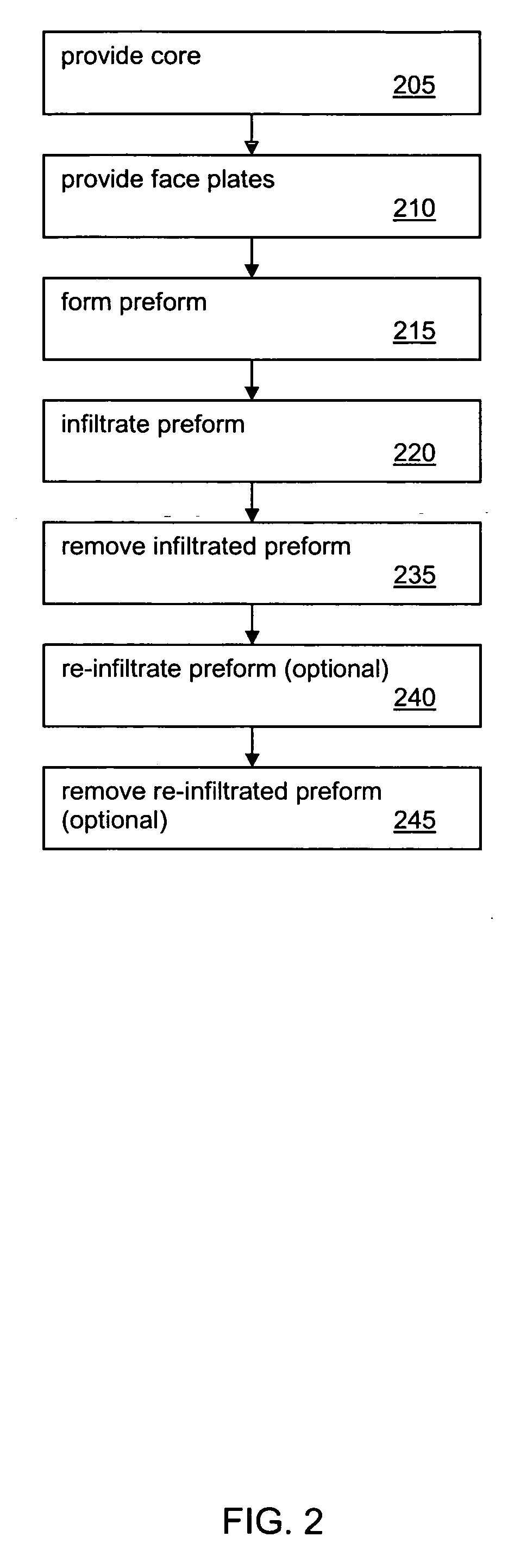
[0020]Embodiments of the invention will be described with reference to the accompanying figures wherein like numbers represent like elements throughout. Further, it is to be understood that the phraseology and terminology used herein is for the purpose of description and should not be regarded as limiting. The use of “including,”“comprising,” or “having” and variations thereof herein is meant to encompass the items listed thereafter and equivalents thereof as well as additional items. The terms “mounted,”“connected,” and “coupled” are used broadly and encompass both direct and indirect mounting, connecting, and coupling. Further, “connected” and “coupled” are not restricted to physical or mechanical connections or couplings.

[0021]Embodiments of the invention provide systems and methods for forming low density ceramic felt material cores which are sandwiched between two CMCs to form a CML possessing a high strength-to-density ratio while maintaining a stiffness required for mechanica...


PUM

PropertyMeasurementUnit
densityaaaaaaaaaa
densityaaaaaaaaaa
densityaaaaaaaaaa

Abstract

The invention provides systems and methods for forming low density ceramic felt material cores which are sandwiched between ceramic matrix composites to form a ceramic matrix laminate possessing a high strength-to-density ratio while maintaining a stiffness required for mechanical applications. The core and face plates are coupled together using a chemical vapor process.

Description

REFERENCE TO RELATED APPLICATION[0001]This application claims the benefit of U.S. Provisional Application No. 60 / 760,990, filed on Jan. 20, 2006, which is incorporated herein by reference in its entirety.BACKGROUND OF THE INVENTION[0002]The invention relates generally to the field of ceramic matrix laminates. More specifically, embodiments of the invention relate to systems and methods for fabricating low density ceramic felt core materials which are sandwiched between two ceramic matrix composites (CMCs).[0003]Sandwich structures are materials that consist of two thin load-bearing face plates joined to a thicker, but less-dense core material. Loads are carried by the face plates with the core acting as a load transfer medium. Depending on the application, the face plates may be fabricated from metal, plywood or fiber reinforced composites. The core may be fabricated from a hard foam or honeycomb material, or a rigid lightweight material.[0004]Sandwich structures are commonly employ...

Claims


Application Information

Patent Timeline
Patent Type & Authority Applications(United States)
IPC IPC(8): B32B3/06B32B5/14B32B5/24
CPCB32B18/00Y10T428/24942C04B35/62281C04B35/62863C04B35/62868C04B35/806C04B2235/483C04B2235/5248C04B2235/5284C04B2235/614C04B2235/77C04B2235/96C04B2237/584C04B2235/656C04B2235/6567C04B2235/6583C04B2235/663C04B2237/361C04B2237/363C04B2237/365C04B2237/38C04B2237/50C04B2237/704B82Y30/00Y10T428/249962Y10T428/31504Y10T428/249957Y10T428/249956C04B35/80C04B35/565
Inventor KMETZ, MICHAEL A.
Owner RTX CORP
Learn More