Dental Vacuum System

Inactive Publication Date: 2007-07-26
MIDMARK
18 Cites 34 Cited by

AI-Extracted Technical Summary

Problems solved by technology

The liquid ring pumps and oil-lubricated rotary vane pumps used in these systems generally require a high degree of maintenance, which in turn results in increased operating costs for such systems.
The efficiency of conventional vacuum systems suffer as a consequence of the energy that must be expended to move the working fluid around in the pumping chamber, and because of the...

Method used

[0020] While FIG. 2 depicts a vacuum assembly 20 including one pump assembly 32, multiple pump assemblies 32 may be coupled to the vacuum reservoir 30 to increase the vacuum capacity of the dental vacuum system 10, as may be desired. FIG. 2B, for example, illustrates another embodiment of a vacuum assembly 20a in accordance with the principles of the present invention wherein first and second pump assemblies 32 are coupled to the vacuum reservoir 30. The pump assemblies are connected in parallel to the vacuum reservoir 30 to thereby increase the vacuum capacity of the dental vacuum system. Such a configuration may require additional fittings to couple the vacuum assembly to the pump assemblies 32 and/or the conduit system 18. A given vacuum system 10 may also include multiple pump assemblies 20 and associated vacuum reservoirs 30 to provide increased flow capacity, as may be desired.
[0024] The pu...

Benefits of technology

[0005] The present invention provides a dental vacuum system that utilizes a positive displacement dry vacuum pump to develop vacuum pressure in a vacuum reservoir. The positive displacement dry vacuum pump operates without a working fluid in its pumping chamber, and therefore exhibits increased efficiency compared to conventional dental va...

Abstract

A dental vacuum system includes a vacuum reservoir and at least one positive displacement dry vacuum pump operatively coupled to the vacuum reservoir to create a vacuum in the reservoir. One or more dental aspirators are coupled to the vacuum reservoir through a conduit system, whereby vacuum pressure developed in the reservoir by the pump is applied to the aspirators. The vacuum pump operates without a working fluid in its pumping chamber.

Application Domain

Saliva removers

Technology Topic

Image

  • Dental Vacuum System
  • Dental Vacuum System
  • Dental Vacuum System

Examples

  • Experimental program(1)

Example

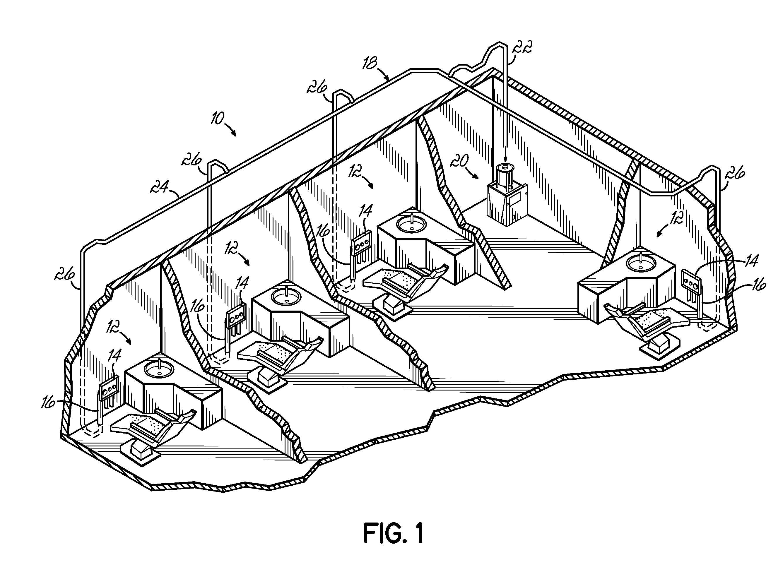
[0018]FIG. 1 illustrates a typical dental office including an exemplary dental vacuum system 10 in accordance with the principles of the present invention. The dental office includes one or more dental operatories 12, each having a station 14 that includes at least one dental aspirator 16. Each aspirator is connected via conduit system 18 to a common vacuum assembly 20 which provides vacuum suction through the conduit system 18 to the aspirators 16. The vacuum assembly 20 will generally be located remote from the operatories 12, such as in a separate room or a utility area of the dental office. The conduit system 18 includes a vacuum line 22 coupled at one end to the vacuum assembly 20. The vacuum line 22 communicates with a distribution line 24 which leads to a plurality of branch lines 26, each coupled to one of the aspirators 16.
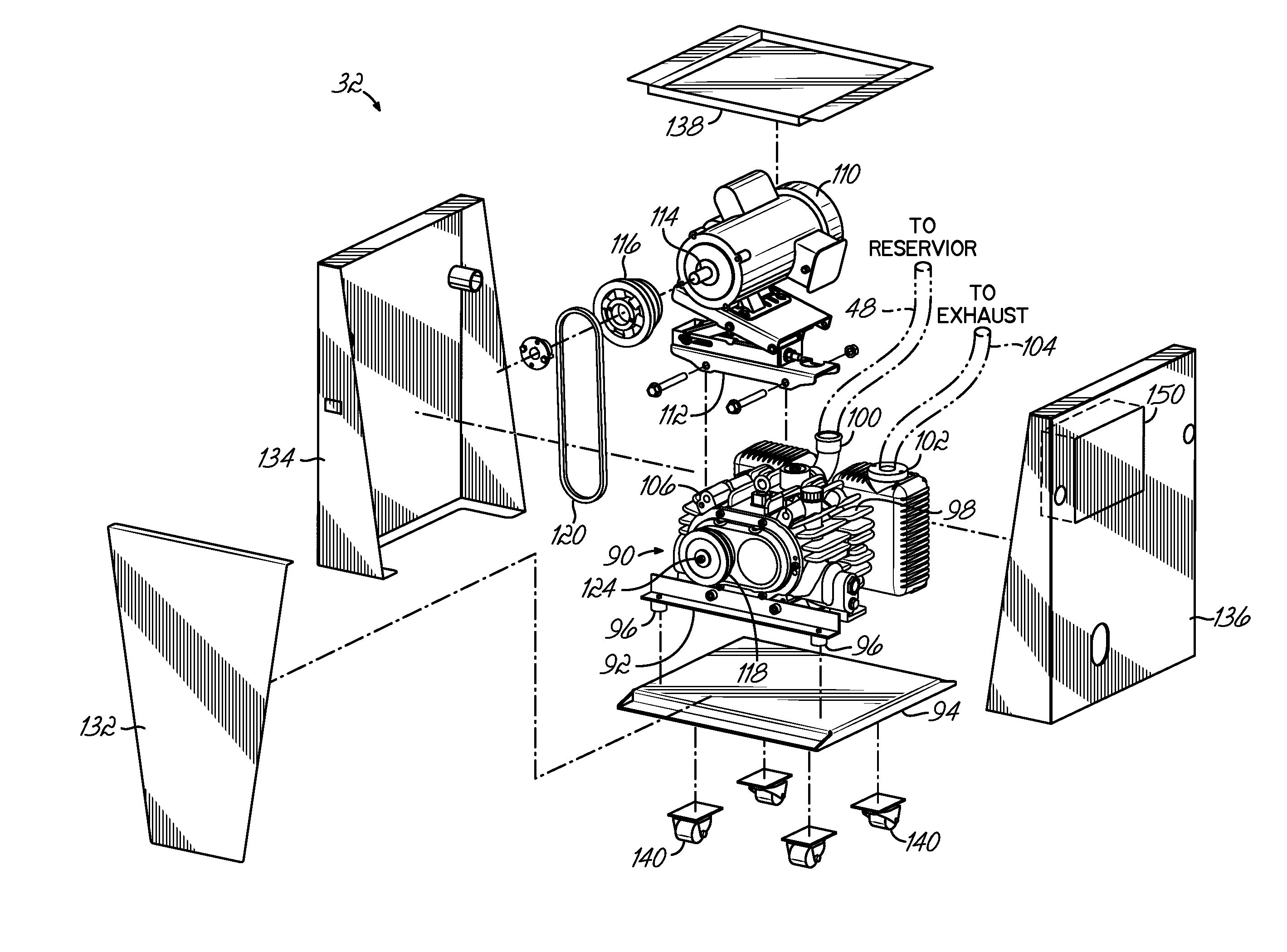
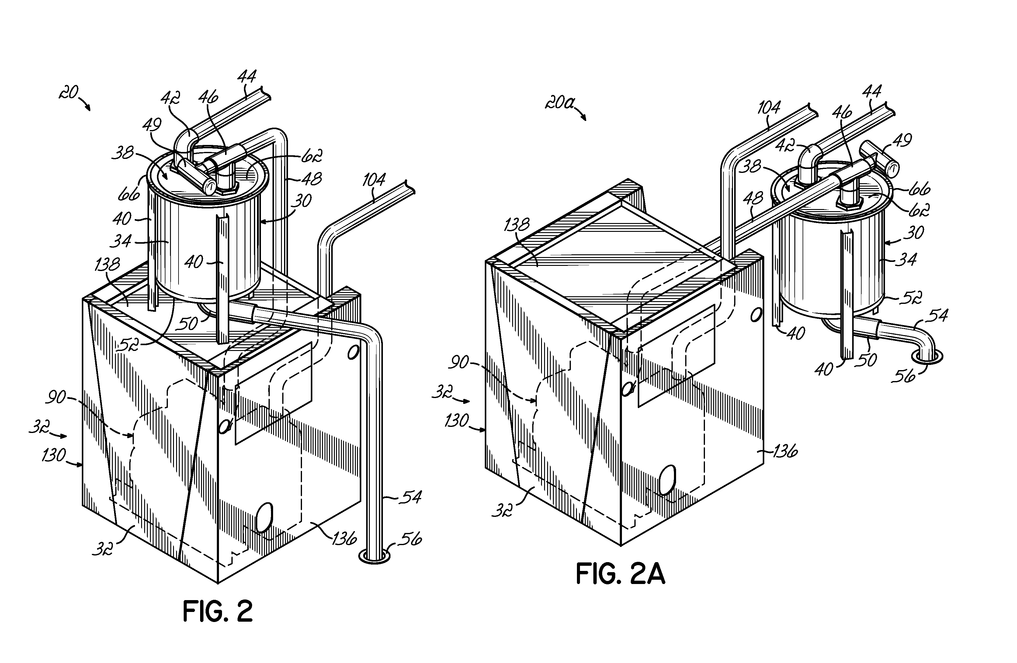
[0019]FIG. 2 illustrates the exemplary dental vacuum assembly 20 in more detail. Dental vacuum assembly 20 includes a vacuum reservoir 30 and a pump assembly 32. In the embodiment shown, reservoir 30 is mounted atop the pump assembly 32, but it will be recognized that the reservoir may alternatively be located adjacent the pump assembly 32, as depicted in FIG. 2A, or at various other locations as may be desired. Vacuum reservoir 30 includes a generally cylindrically-shaped tank 34 having an open end 36 (see FIG. 3) that is sealed by a reservoir lid 38. The reservoir 30 is supported by downwardly extending legs 40 provided on an outer periphery of the tank 34. In the embodiment shown, a first fitting 42 is coupled, for example, by flexible tubing 44, to the conduit system 18 to provide fluid communication between the vacuum reservoir 30 and the conduit system 18. A second fitting 46 is coupled, for example, by a flexible tubing 48, to the pump assembly 32 to provide fluid communication between the vacuum reservoir 30 and the pump assembly 32, as will be described in more detail below. The second fitting 46 may include a vacuum relief valve 49 that is adjustable to set a desired vacuum pressure in the vacuum reservoir 30. In the embodiment shown, the fittings 42, 46 are provided on the reservoir lid 38, but it will be recognized that the fittings 42, 46 may alternatively be provided on the tank 34. A drain fitting 50 provided on a lower end 52 of the tank 34 is coupled by a flexible tubing 54 to a floor drain 56. The drain fitting 50 may include a check valve (not shown) which is operative to prevent the flow of fluids and other material to the floor drain 56 when the vacuum assembly 20 is operating to provide vacuum suction to the aspirators 16. When the vacuum system 10 has been shut off, the check valve opens to permit liquids and other materials accumulated in the vacuum reservoir 30 to exit the drain fitting 50 to the floor drain 56.
[0020] While FIG. 2 depicts a vacuum assembly 20 including one pump assembly 32, multiple pump assemblies 32 may be coupled to the vacuum reservoir 30 to increase the vacuum capacity of the dental vacuum system 10, as may be desired. FIG. 2B, for example, illustrates another embodiment of a vacuum assembly 20a in accordance with the principles of the present invention wherein first and second pump assemblies 32 are coupled to the vacuum reservoir 30. The pump assemblies are connected in parallel to the vacuum reservoir 30 to thereby increase the vacuum capacity of the dental vacuum system. Such a configuration may require additional fittings to couple the vacuum assembly to the pump assemblies 32 and/or the conduit system 18. A given vacuum system 10 may also include multiple pump assemblies 20 and associated vacuum reservoirs 30 to provide increased flow capacity, as may be desired.
[0021]FIG. 3 illustrates the attachment of the reservoir lid 38 to the tank 34. In the embodiment shown, the open end 36 of the tank 34 includes an annular flange 60. The reservoir lid 38 has a generally depressed central portion 62 and a corresponding annular flange 64 sized and shaped to engage the annular flange 60 of the tank 34. The reservoir lid 38 is sealingly secured to the tank 34 by a sealing gasket 66 that fits over the respective outer peripheries of the tank 34 and lid flanges 60, 64. In one embodiment, the gasket 66 is formed from polymeric material, such as Neoprene®, however, various other materials suitable for retaining the reservoir lid 38 on the tank 34 while sealing the tank 34 may alternatively be used.
[0022] In the embodiment shown in FIG. 4, the gasket 66 comprises a back wall 68 having oppositely disposed first and second ends 70, 72. First and second opposed sidewalls 74, 76 proximate the first and second ends 70, 72 of the back wall 68 extend generally perpendicularly from the back wall 68 to define an annular channel section between the sidewalls 74, 76. The gasket 66 further includes an intermediate wall 78 disposed between the sidewalls 74, 76 and separating the channel into first and second portions 80, 82. The gasket 66 is sized such that the annular flange 64 of the lid 38 is received within the first channel portion 80 and the annular flange 64 of the tank 34 is received in the second channel portion 82 of the gasket 66. The sidewalls 74, 76 may be angled or tapered in a direction toward intermediate wall 78 to create a narrowing of the first and second channel portions 80, 82 so that gasket 66 fits snuggly against the flanges 60, 64 and seals the lid 38 to the tank 34. The gasket 66 may first be placed over the annular flange 64 of the reservoir lid 38 and then the lid 38 and gasket 66 may be fitted over the annular flange 60 of the tank 34 to thereby sealingly secure the lid 38 to the tank 34. Accordingly, no clamps, fasteners or other hardware is needed to sealingly secure the reservoir lid 38 to the tank 34.
[0023] Referring now to FIG. 5, the pump assembly 32 will be described in more detail. Pump assembly 32 includes a rotary claw pump 90, such as Part No. 029-3715-00 available from Midmark Corporation of Versailles, Ohio, mounted to a support frame 92 and supported on a base plate 94. Resilient, vibration isolators 96 may be provided between the support frame 92 and the base plate 94 to attenuate vibration of the pump 90. The pump 90 includes a pump chamber 98 which houses rotating claws (not shown) and operates without working fluid to develop vacuum pressure, as known in the art. An inlet port 100 is coupled to the vacuum reservoir 30 by the flexible hose 48, as depicted in FIG. 2, and an exhaust port 102 may be coupled to an exhaust line 104 routed to an appropriate location, such as a location outside the office. The pump 90 further includes a gearbox 106 for driving the rotary claws within the pump chamber 98. Motor 110 is mounted atop the pump 90 by a motor mount 112. An output shaft 114 on the motor is coupled by sheaves 116, 118 and a belt 120 to an input drive shaft 124 on the gearbox 106. The motor mount 112 is adjustable to position the motor 110 relative to the pump 90 whereby the tension of the drive belt 120 may be adjusted as required. Sheaves 116, 118 and belt 120 may be removed and replaced with sheaves of different diameters and a corresponding, appropriately-sized belt to vary the speed at which the motor 110 drives the rotary claws of the pump chamber 98, thereby varying the flow through the pump 90.
[0024] The pump 90 and motor 110 are enclosed in a housing 130 comprising a front wall 132 and first and second sidewalls 134,136 which may be secured to the base plate 94 by fasteners (not shown). A rear side of the pump assembly 32, opposite the front wall 132 is generally open to facilitate routing hoses 48 between the reservoir 30 and the pump 90, and to facilitate dissipating heat generated by the pump 90. The housing 130 further includes a panel 138 which may be useful for mounting the vacuum reservoir 30 above the pump assembly 32, as generally depicted in FIG. 2. Pump assembly 32 may also include casters 140 provided beneath the base plate 94 to facilitate installation of the vacuum assembly 20 in a dental office or other facility. A controller 150 may be mounted within housing 130 to provide power to motor 110 and may include PLC's or various other devices to control operation of the vacuum system 10.
[0025] In use, the vacuum assembly 30 is placed at a desired location, such as within a utility room of a dental office, and the inlet port 100 of the pump 90 is coupled to the second fitting 46 on the vacuum reservoir 30, such as by flexible hose 48. The first fitting 42 on the vacuum reservoir 30 is coupled via a flexible hose 44 and conduit system 18 to one or more dental aspirators 16, and the drain fitting 50 is coupled to a floor drain 56 or other appropriate disposal structure, such as by flexible hose 54. The exhaust port 102 of the pump 90 is coupled by a flexible hose to a vent or other appropriate location. Pump 90, driven by motor 110 evacuates air from vacuum reservoir 30 to develop a vacuum within the vacuum reservoir 30. The vacuum pressure is applied to the individual aspirators 16 through the conduit system 18. Because pump 90 is a dry vacuum pump, no working fluid is required in the pumping chamber 98, and the vacuum system 10 therefore does not require constant monitoring or periodic replacement of a working fluid, as is common with conventional dental vacuum systems.
[0026] A dental vacuum system in accordance with the principles of the present invention, such as the exemplary vacuum systems shown and described herein, provides a long service-life requiring minimal maintenance and does not require replacement of internal parts due to wear. The system is air cooled and has no internal parts that must be replaced due to wear. These features, along with reduced power requirements compared to known vacuum systems, result in low operating costs.
[0027] While the present invention has been illustrated by the description of one or more exemplary embodiments thereof, and while the embodiments have been described in considerable detail, they are not intended to restrict or in any way limit the scope of the appended claims to such detail. Additional advantages and modifications will readily appear to those skilled in the art. The invention in its broader aspects is therefore not limited to the specific details, representative apparatus and method and illustrative examples shown and described. Accordingly, departures may be made from such details without departing from the scope or spirit of the general inventive concept.

PUM

no PUM

Description & Claims & Application Information

We can also present the details of the Description, Claims and Application information to help users get a comprehensive understanding of the technical details of the patent, such as background art, summary of invention, brief description of drawings, description of embodiments, and other original content. On the other hand, users can also determine the specific scope of protection of the technology through the list of claims; as well as understand the changes in the life cycle of the technology with the presentation of the patent timeline. Login to view more.

Similar technology patents

Classification and recommendation of technical efficacy words

Why Eureka
Try Eureka