Device and method for calibrating a laser system

a laser system and device technology, applied in laser surgery, medical science, surgery, etc., can solve the problem of not ending the calibration process

Inactive Publication Date: 2007-07-26
TECHNOLAS PERFECT VISION
View PDF29 Cites 36 Cited by
  • Summary
  • Abstract
  • Description
  • Claims
  • Application Information

AI Technical Summary

Benefits of technology

[0007] Additionally, for all calibration evaluations, the system is provided with an imaging device for identifying whether LIOB is induced. A measurement device is also provided for measuring the distance “d” and a radial distance “r” of the final LIOB locations from the central axis to calibrate the laser beam. In this manner, the control of the laser beam may be calibrated.
[0008] During operation of the system, a plurality of final LIOB locations may be used to calibrate a “tilt” and a “decenter” for the laser beam. Further, a plurality of final LIOB locations may be used to create test patterns from laser beams having different energies. Specifically, energies are provided in a range between a low energy and a high energy, yielding an energy density at the focal point below the energy density threshold for LIOB of the calibration member, and a high energy density at the focal point above the energy density threshold for LIOB of the calibration member, to determine an energy density for the focal spot of the laser beam. Further, a plurality of test patterns may be compared with each other to determine a uniformity for energy density in the focal spot of the laser beam.

Problems solved by technology

This, however, does not end the calibration process.

Method used


Image

  • Device and method for calibrating a laser system
  • Device and method for calibrating a laser system
  • Device and method for calibrating a laser system

Examples


Embodiment Construction

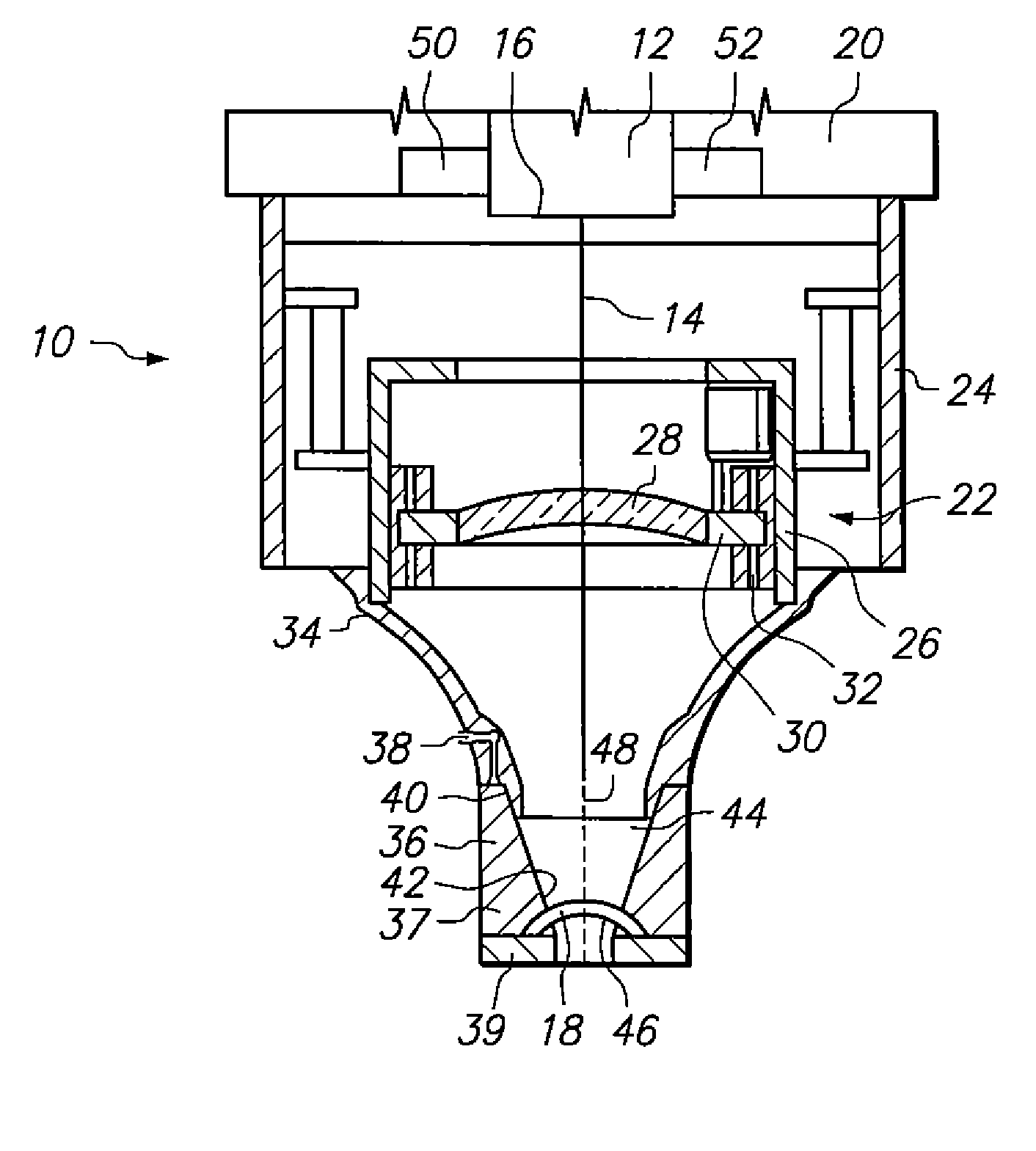
[0015] Referring initially to FIG. 1, a system for calibrating a, preferably femtosecond, laser system in accordance with the present invention is shown and generally designated 10. As shown, the system 10 includes a laser unit 12 for generating the laser beam 14. Further, the laser unit 12 defines a base datum 16 that will be used as a spatial reference for the calibration procedures performed by the system 10. As will be explained below, the system 10 relies on a calibration member 18 to calibrate the laser unit 12. However, in order to properly explain the system 10, the general components used to focus the laser beam 14 are first identified and discussed.

[0016] Structurally, the laser unit 12 is mounted on a housing 20. The laser unit 12 can be of any type well known in the art which is capable of generating an ophthalmic laser beam 14. Furthermore, while a specific optical arrangement that can be used to direct the laser beam 14 through system 10 is shown, it is to be apprecia...


PUM


Abstract

A device for calibrating a laser beam system includes a calibration member having a surface positioned at a predetermined distance from the base datum of the unit. Further, the system includes a mechanism for focusing the beam to a focal point and for moving the focal point relative to the surface of the calibration member. When the focal point reaches the surface of the calibration member, Laser Induced Optical Breakdown (LIOB) is induced. Thereafter, the position of the location of LIOB may be measured relative to the base datum to calibrate the laser beam. Further, patterns may be applied to the calibration member using LIOB to calibrate tilt/decenter of the beam and to determine the energy density and uniformity in the focal spot of the laser beam.

Description

FIELD OF THE INVENTION [0001] The present invention pertains generally to laser system calibration procedures. More particularly, the present invention relates to systems and methods for performing laser system calibration wherein the laser beam causes Laser Induced Optical Breakdown (LIOB) in a reference material. The present invention is particularly, but not exclusively, useful as a system and method for precise calibration of a laser system via the identification and measurement of locations where LIOB occurs in a reference material. BACKGROUND OF THE INVENTION [0002] For a laser system used in ophthalmic surgery, it is critical that the laser beam be properly focused, and that the position of the beam's focal point with respect to the laser generating unit be known. Further, due to the curved nature of the cornea, a beam that is to be used in ophthalmic surgery must exhibit proper depth and avoid tilt and lateral displacement (decentration). Additionally, the focal point of the...

Claims


Application Information

Patent Timeline
Patent Type & Authority Applications(United States)
IPC IPC(8): A61B18/18
CPCA61B2017/00712A61F9/008A61F2009/00872A61F9/0084A61F2009/00855A61F9/00825
Inventor KESSLER, RALFMARTIN, MARCELWUHL, STEFANKUHN, TOBIASVON PAPE, ULRICH
Owner TECHNOLAS PERFECT VISION
Why Eureka
Try Eureka