
Dual synchro-resonant electrosurgical apparatus with bi-directional magnetic coupling

a dual-synchro-resonant, electrosurgical technology, applied in the field of electrosurgical systems, can solve the problem that current state of the art electrosurgical generators do not provide sufficient rf energy for prescribed periods of tim

Active Publication Date: 2007-07-26
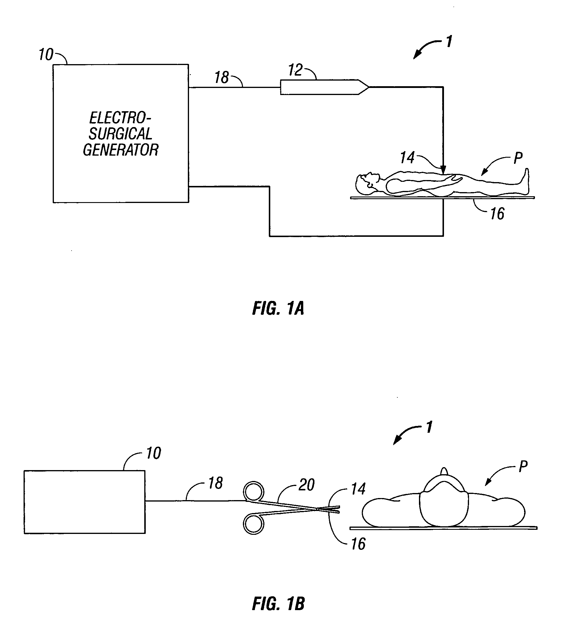
COVIDIEN AG
View PDF75 Cites 73 Cited by
  • Summary
  • Abstract
  • Description
  • Claims
  • Application Information

AI Technical Summary

Benefits of technology

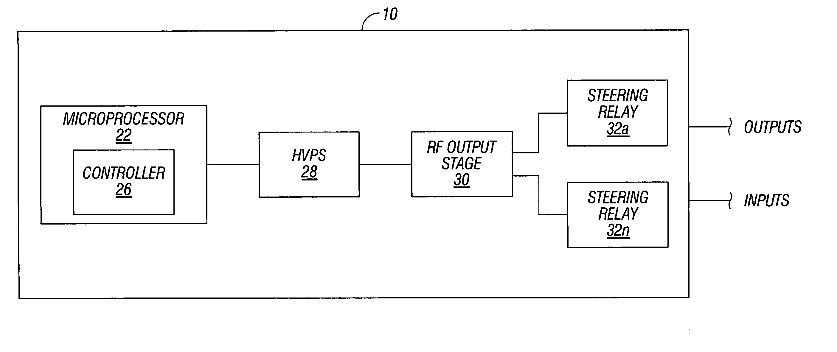
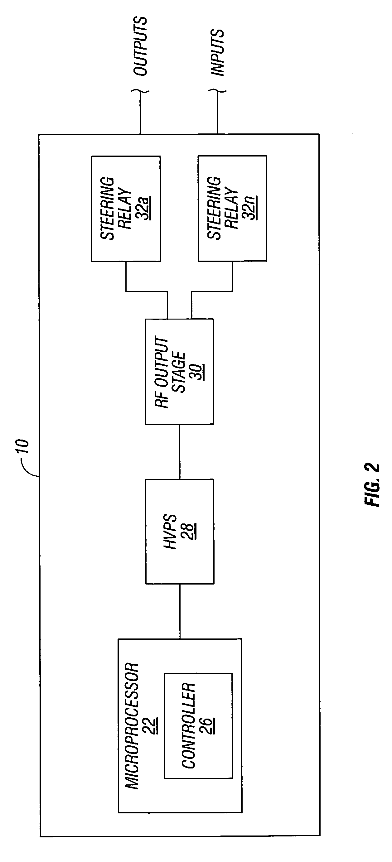
[0010] The first parallel inductor-capacitor resonant circuit is configured to produce a first positive half-sinusoidal waveform and the second parallel inductor-capacitor resonant circuit is configured to produce a second positive half-sinusoidal waveform, which is phase-delayed 180 degrees with respect to the first positive half-sinusoidal waveform. The RF output stage further includes a transformer having a primary winding and a secondary winding, which is a patient connective side, and a series inductor-capacitor resonant circuit. The series inductor-capacitor resonant circuit and the transformer are configured to generate a sinusoidal waveform. The RF output stage further includes a switching module which, in response to the control signals, adjusts the first and second half-sinusoidal waveforms thereby producing the sinusoidal waveforms suitable for the at least one electrosurgical mode. The first and second waveforms generate in-sync ripple components at the primary winding, which generate opposing magnetic fields thereby preventing transfer of parasitic RF harmonic ring energy to the secondary winding.

Problems solved by technology

Current state of the art electrosurgical generators do not provide sufficiently powerful RF energy for prescribed periods of time.

Method used


Image

  • Dual synchro-resonant electrosurgical apparatus with bi-directional magnetic coupling
  • Dual synchro-resonant electrosurgical apparatus with bi-directional magnetic coupling
  • Dual synchro-resonant electrosurgical apparatus with bi-directional magnetic coupling

Examples


Embodiment Construction

[0015] Particular embodiments of the present disclosure will be described herein below with reference to the accompanying drawings. In the following description, well-known functions or constructions are not described in detail to avoid obscuring the present disclosure in unnecessary detail.

[0016] The present disclosure includes an RF electrosurgical apparatus having a dual synchronous-resonant, magnetically coupled architecture which generates multi-mode and multi-frequency, monopolar, bipolar, and sealing type RF energy. RF energy is developed using a phase correlated dual drive network having a single or integer multiple number of drive pulses applies to switching devices which generate the dual synchronous-resonant RF energy, coupled in the magnetic field of a patient connective isolating transformer. Magnetically coupled RF energy is used to both generate the applied RF, used in clinical applications, and simultaneously cancel the unwanted parasitic RF harmonics during RF off ...


PUM


Abstract

An electrosurgical generator is disclosed, which includes an RF output stage connected to a DC power supply and first and second connections. The first connection includes a first switching component and a first parallel inductor-capacitor resonant circuit. The second connection includes a second switching components and a second parallel inductor-capacitor resonant circuit. The first and second switching components are configured to open and close at a predetermined frequency based on a phase-correlated dual drive signal emitted by a driver and are in a 180 degree out-of-phase relationship. The first parallel inductor-capacitor resonant circuit is further configured to produce a first half-sinusoidal waveform and the second parallel inductor-capacitor resonant circuit is configured to produce a second half-sin half-sinusoidal waveform. The RF output stage further includes a transformer having a primary winding and a secondary winding and a series inductor-capacitor resonant circuit, which are configured to generate a sinusoidal waveform.

Description

BACKGROUND [0001] 1. Field [0002] The present disclosure relates generally to electrosurgical system, and more specifically, to an electrosurgical generator for delivering high power radiofrequency (RF) energy using multiple resonant inductor-capacitor (LC) networks and a switching module for adjusting the energy to make it suitable for a variety of electrosurgical procedures. [0003] 2. Description of the Related Art [0004] Electrosurgery involves application of high radio frequency (RF) electrical current to a surgical site to cut, ablate, or coagulate tissue. In monopolar electrosurgery, a source or active electrode delivers radio frequency energy from the electrosurgical generator to the tissue and a return electrode carries the current back to the generator. In monopolar electrosurgery, the source electrode is typically part of a surgical instrument held by the surgeon and applied to the tissue to be treated. A patient return electrode is placed remotely from the active electrod...

Claims


Application Information

Patent Timeline
Patent Type & Authority Applications(United States)
IPC IPC(8): A61B18/18
CPCA61B18/12A61B2018/124A61B2018/0066A61B18/1206
Inventor ORSZULAK, JAMES H.
Owner COVIDIEN AG
Learn More