Device with actuatable fluid-column occluder for prevention of embolization

a fluid-column occluder and device technology, applied in balloon catheters, medical science, surgery, etc., can solve the problems of significant health problems of patients, complex fabrication of expandable mechanical structures, and add undesired to the overall collapsed profile of occlusion guidewires

Active Publication Date: 2007-07-26
MEDTRONIC VASCULAR INC
View PDF16 Cites 6 Cited by
  • Summary
  • Abstract
  • Description
  • Claims
  • Application Information

AI Technical Summary

Benefits of technology

This patent describes a protective device that can be used during medical procedures to prevent blood clots from causing damage. It consists of two parts: an outer tube and an inner tube which moves inside it. There's also a mechanism that causes the device to expand when its moved forward in order to block any potentially harmful material. The design helps keep the device secure while moving through the patient's body and ensures that no liquid leaks out of it. Overall, this device provides better safety during minimally invasive surgeries where blood clots could cause serious problems.

Problems solved by technology

The technical problem addressed in this patent text relates to finding ways to protect against potentially harmful debris or fragments that are generated during medical treatments of cardiovascular disease. Current methods involve the use of various tools like filters, occlusion guides, and suction systems but they come with their own limitations including complexity and added time requirements. Therefore, there is a need for a simpler and lower-profile solution to mitigate the risks posed by embolic materials while still achieving effective results without causing further damage to the patient.

Method used


Image

  • Device with actuatable fluid-column occluder for prevention of embolization
  • Device with actuatable fluid-column occluder for prevention of embolization
  • Device with actuatable fluid-column occluder for prevention of embolization

Examples


Embodiment Construction

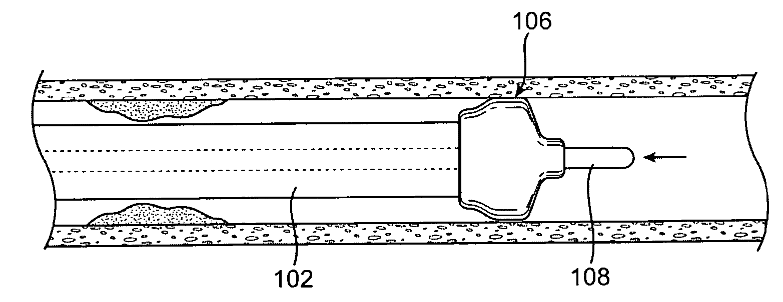
[0017] Specific embodiments of the present invention are now described with reference to the figures, wherein like reference numbers indicate identical or functionally similar elements. The terms “distal” and “proximal” are used in the following description with respect to a position or direction relative to the treating clinician. “Distal” or “distally” are a position distant from or in a direction away from the clinician. “Proximal” and “proximally” are a position near or in a direction toward the clinician.

[0018] While the following description generally refers to a distal protection device, it should be understood that the invention is also applicable to a proximal protection device, wherein the occluder may be deployed proximally of a treatment site to block flow upstream of the site. A treatment apparatus, such as a catheter, may be delivered via a through lumen in the proximal protection device to provide therapy at the site. See lumen 509 in FIG. 5. Debris generated during ...


PUM

PropertyMeasurementUnit
Elastomericaaaaaaaaaa
Volumeaaaaaaaaaa
Radiopacityaaaaaaaaaa

Abstract

A flexible elongate device having a distally mounted occluder for collecting particulate debris in a body lumen. The occluder containing a fixed amount of fluid is reversibly expandable by push-pull actuation from a contracted configuration to a deployed configuration wherein the occluder is expanded into sealing engagement with the wall of the body lumen. The occluder has a distal end axially secured to an elongate inner member and a proximal end attached to a distal end of an outer tubular member. The occluder has an impermeable occluder casing for containing the occluder fluid. The elongate inner member is slidable within the outer tubular member such that relative longitudinal movement between the elongate inner member and outer tubular member changes the length of the occluder and thus redistributes the occluder fluid within the occluder casing to transform the occluder between its contracted and deployed configurations.

Description


Claims


Application Information

Patent Timeline
Owner MEDTRONIC VASCULAR INC
Why Eureka
Try Eureka