Anchoring system for medical implant

a technology of an anchoring system and an implant, which is applied in the field of medical implants, can solve problems such as incomplete coaptation of valve leaflets, and achieve the effect of reducing or eliminating the regurgitation of mitral valves

Inactive Publication Date: 2007-07-26
EDWARDS LIFESCIENCES CORP
View PDF82 Cites 47 Cited by
  • Summary
  • Abstract
  • Description
  • Claims
  • Application Information

AI Technical Summary

Benefits of technology

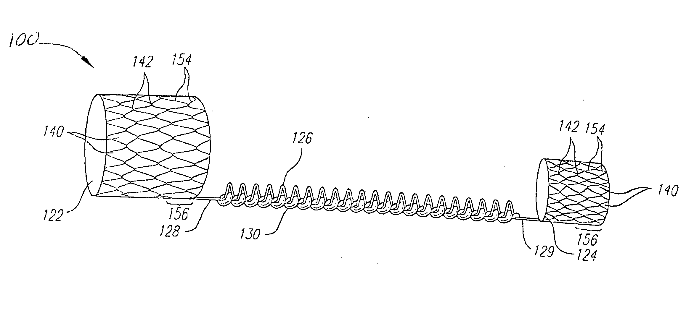
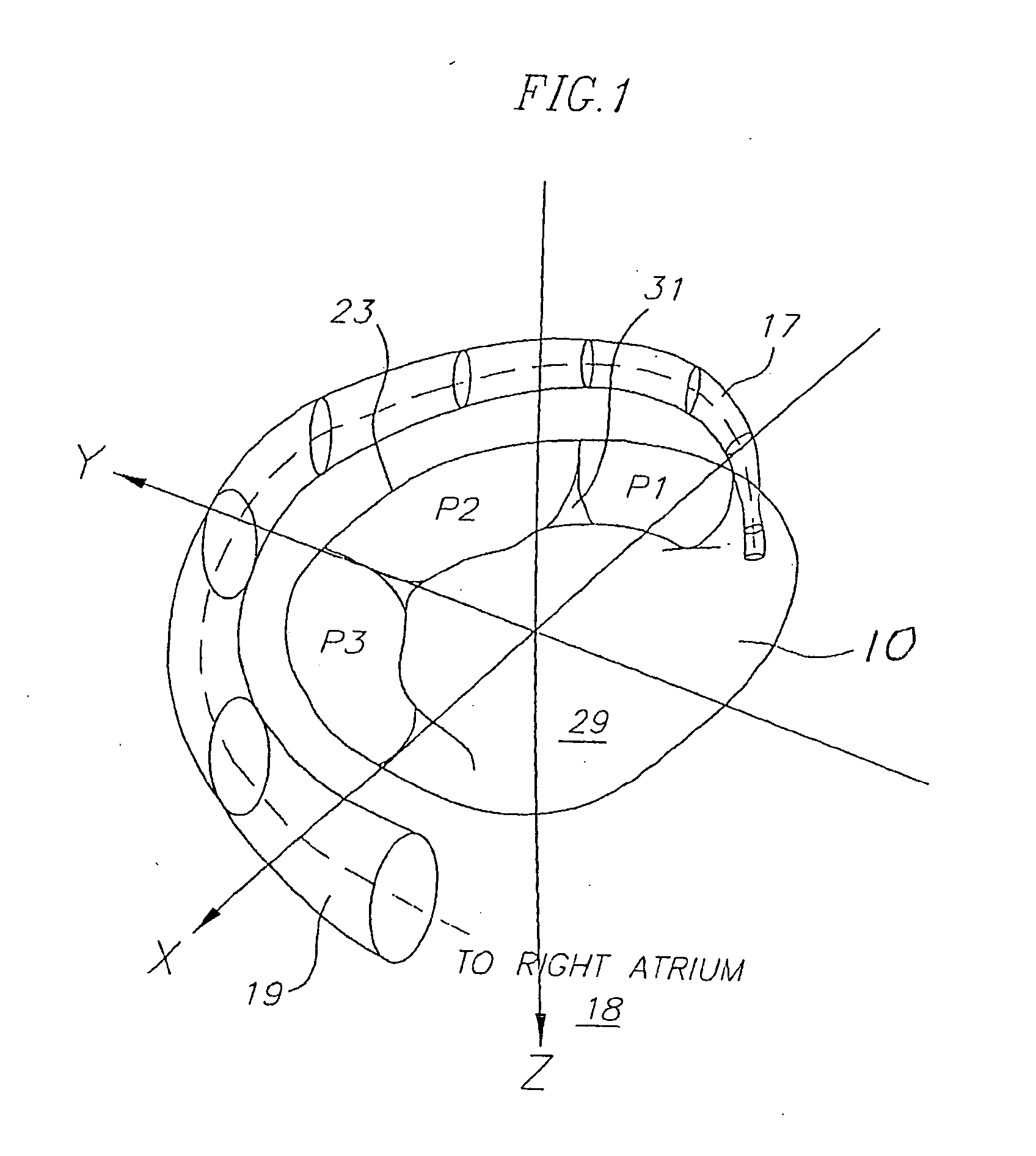
[0007] Preferred embodiments of the present invention provide an implant, and method of use therefore, configured for placement in a body lumen such as the coronary sinus. The implant has a first anchor, a second anchor, and an elongate bridge portion that is secured to the first and second anchors. The first and second anchors are configured to radially expand into contact with the walls of the body lumen so that the anchors are secured within the body lumen. After deployment in a coronary sinus of a heart, the implant changes shape to apply a reshaping force along the coronary sinus axis and the posterior portion of a mitral annulus. The applied force restores proper mitral valve leaflet coaptation and thereby reduces or eliminates mitral valve regurgitation.
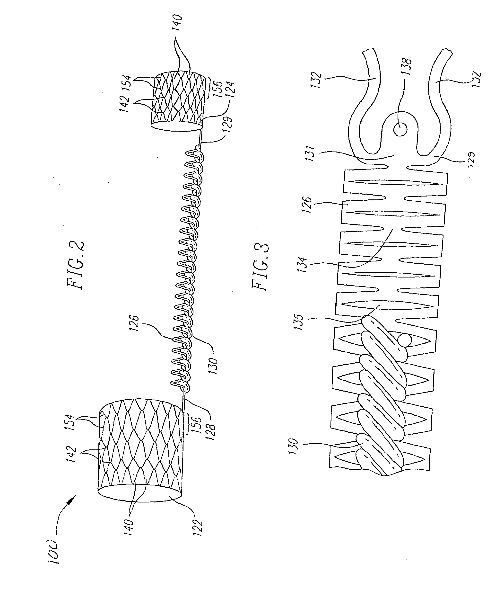
[0008] In one preferred aspect of the present invention, an implant for treating mitral valve annulus dilatation comprises a bridge in the form of a shape-changing member having a proximal end portion and a distal end portion. The shape-changing member has first shape and a second shape. A displaceable or removable material is disposed along the shape-changing member for temporarily maintaining the shape-changing member in the first shape. The displaceable material is configured to be displaced for allowing the shape-changing member to transition from the first shape to the second shape after implantation in the coronary sinus. A proximal anchor is coupled to the proximal end portion of the shape-changing member and a distal anchor is coupled to the distal end portion of the shape-changing member. In an advantageous feature, the proximal and distal anchors are configured with improved structures such that the proximal end portion of the shape-changing member overlaps with at least a portion of the proximal anchor and the distal end portion of the shape-changing member overlaps with at least a portion of the distal anchor. Because the shape-changing member overlaps the anchors, the shape-changing member comprises a larger portion of the overall length of the implant, thereby increasing the effectiveness and adaptability of the implant.
[0010] In another variation, the shape-changing member is flexibly coupled to the proximal and distal anchors, such as by one or more flexible mechanical linkages. In preferred embodiments, the mechanical linkages exhibit sufficient flexibility for reducing stress concentrations at the attachment points.
[0015] In another variation, at least one of the proximal and distal stents has a flared end region for improved anchoring.
[0016] In another variation, the shape-changing member is rotatably or hingedly coupled to at least one of the proximal and distal anchors. A rotatable or hinged attachment allows articulation of the shape-changing member relative to the anchors such that the shape-changing member and anchors can move semi-independently. This feature advantageously allows the implant to conform to tortuous regions of the coronary sinus without creating stress concentrations at the attachment points.
[0017] In another preferred aspect of the present invention, a medical implant comprises a proximal anchor configured for engagement to an ostium of a coronary sinus when in a deployed position, a distal anchor configured for engagement with an inner wall of a coronary sinus when in a deployed position, and an elongate bridge extending between the proximal and distal anchors, the elongate bridge configured for applying a reshaping force along an annulus of a mitral valve. The proximal and distal anchors are preferably capable of pivoting relative to the elongate bridge along at least one axis. This feature allows the bridge to extend away from the anchors at a different relative angle and thereby reduces or eliminates stress concentrations at the attachment points. This type of coupling also advantageously allows the anchors and bridge to move semi-independently of each other. Preferably, the elongate bridge is formed of a shape-memory material and the bridge is maintained in an elongated state by a resorbable material during implantation. The bridge is biased to transition to a contracted state as the resorbable material is gradually resorbed after implantation.

Problems solved by technology

These geometric alterations can result in incomplete coaptation of the valve leaflets during systole.

Method used


Image

  • Anchoring system for medical implant
  • Anchoring system for medical implant
  • Anchoring system for medical implant

Examples


Embodiment Construction

[0037] Various embodiments of the present invention depict medical implants and methods of use that are well-suited for treating mitral valve regurgitation. However, it should be appreciated that the principles and aspects of the embodiments disclosed and discussed herein are also applicable to other devices having different structures and functionalities. For example, certain structures and methods disclosed herein may also be applicable to other medical devices configured for implantation in a blood vessel. Furthermore, certain aspects of the present invention may also be used in conjunction with other medical devices or other procedures not explicitly disclosed. The manner of adapting the embodiments described herein to various other devices and functionalities will become apparent to those of skill in the art in view of the description that follows.

[0038] As used herein, “distal” means the direction of a device as it is being inserted into a patient's body or a point of referen...


PUM


Abstract

Embodiments of the invention provide a medical implant, and method for deploying the same, configured for placement in a body lumen such as a coronary sinus, as may be desired to treat a regurgitant mitral valve. The implant includes a proximal anchor, a distal anchor, and an elongate bridge extending between the proximal and distal anchors. The anchors are configured to be delivered to a desired deployment site within the body lumen in a collapsed or contracted condition and then expanded to engage the walls of the body lumen. The bridge is preferably a shape-changing member configured to contract after delivery into the coronary sinus for applying a compressive force to the annulus of the mitral valve. The proximal and distal anchoring mechanisms preferably overlap the proximal and distal end portions of the bridge, thereby providing the implant with a longer bridge having greater contraction.

Description

RELATED APPLICATIONS [0001] The present invention claims priority to Provisional Application No. 60 / 749,215, filed on Dec. 9, 2005, entitled “Device and Method For Treating a Mitral Valve.”FIELD OF THE INVENTION [0002] The present invention relates to a medical implant, and more particularly to a medical implant configured to reshape the annulus of a mitral valve. BACKGROUND OF THE INVENTION [0003] Heart valve regurgitation, or leakage from the outflow to the inflow side of a heart valve, is a condition that occurs when a heart valve fails to close properly. Regurgitation through the mitral valve is often caused by changes in the geometric configurations of the left ventricle, papillary muscles, and mitral valve annulus. Similarly, regurgitation through the tricuspid valve is often caused by changes in the geometric configurations of the right ventricle, papillary muscles, and tricuspid annulus. These geometric alterations can result in incomplete coaptation of the valve leaflets du...

Claims


Application Information

Patent Timeline
Patent Type & Authority Applications(United States)
IPC IPC(8): A61F2/06
CPCA61F2/2451
Inventor BOBO, DONALDBOURANG, HENRYCORSO, PHILIPWERTENBERG, WILLIAMCHAU, MARKPOPP, MICHAEL
Owner EDWARDS LIFESCIENCES CORP
Why Eureka
Try Eureka