Custom-length self-expanding stent delivery systems with stent bumpers

a stent and bumper technology, applied in the field of custom-length self-expanding stent delivery systems with stent bumpers, can solve the problems of stent face, long length of stent, large vessel volume, etc., and achieve the effect of preventing distal migration of stent segments and stable in the vessel

Active Publication Date: 2005-12-29
JW MEDICAL SYSTEMS LTD
View PDF99 Cites 205 Cited by
  • Summary
  • Abstract
  • Description
  • Claims
  • Application Information

AI Technical Summary

Benefits of technology

[0009] In a number of embodiments, the stent bumper in the expanded shape has an outer diameter sized to contact an inner wall of the body lumen. The bumper may thus prevent distal migration of the stent segments and be stable in the vessel, without tilting, deflecting or slipping. In some embodiments, at least a portion of the stent bumper includes a lubricious surface for contacting one or more of the stent segments. For example, a proximal surface or portion of the stent bumper may have such a coating.
[0014] In an alternative embodiment, before expanding the balloon, a portion of the balloon is exposed from the distal end of an inner sheath that is disposed over the balloon. Such a method may optionally further involve, before releasing the second stent segment: exposing an additional portion of the balloon from the distal end of the inner sheath, the additional portion disposed within the expanded first stent segment; and inflating the balloon, wherein the balloon engages the second stent segment during expansion thereof to maintain its position relative to the delivery catheter and the first segment. In some embodiments, inflating the additional portion of the balloon further expands the expanded first stent segment.

Problems solved by technology

While self-expanding stents have demonstrated promise in various applications, such stents face a number of challenges.
One such challenge is that in some cases the disease in a vessel may be so extensive that a stent of very long length, e.g. 30-200 mm, is called for.
Currently available stents are typically less than 30 mm in length, and suffer from excessive stiffness if made longer.
Such stiffness is particularly problematic in peripheral vessels such as the femoral arteries, where limb movement requires a high degree of flexibility in any stent implanted in such vessels.
However, this approach has suffered from several drawbacks.
In order to place multiple stents, multiple catheters must be inserted, removed and exchanged, heightening risks, lengthening procedure time, raising costs, and causing excessive material waste.
In addition, the deployment of multiple stents end-to-end suffers from the inability to accurately control stent placement and the spacing between stents.
This results in overlap of adjacent stents and / or excessive space between stents, which is thought to lead to complications such as restenosis, the renarrowing of a vessel following stent placement.
With self-expanding stents the problem is particularly acute, because as the stent is released from the catheter, its resiliency tends to cause it to eject or “watermelon seed” distally from the catheter tip by an unpredictable distance.
During such deployment, the stent may displace not only axially but rotationally relative to the delivery catheter resulting in inaccurate, uncontrollable, and unpredictable stent placement.
Interleaving stents or stent segments such as those disclosed in co-pending U.S. patent application Ser. No. 10 / 738,666 (Attorney Docket No. 021629-000510US), filed Dec. 16, 2003, which is incorporated herein by reference, present even greater challenges to conventional delivery systems.
Conventional delivery systems suffer from the inability to control both the axial and rotational positions of self-expanding stents as they are deployed.
“Watermelon seeding” of self-expanding stents, where the resiliency of the stents causes them to eject distally from the catheter tip by an unpredictable distance, continues to be a challenge.

Method used


Image

  • Custom-length self-expanding stent delivery systems with stent bumpers
  • Custom-length self-expanding stent delivery systems with stent bumpers
  • Custom-length self-expanding stent delivery systems with stent bumpers

Examples


Embodiment Construction

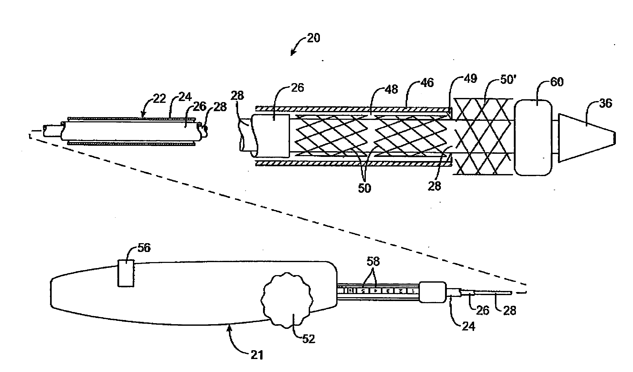
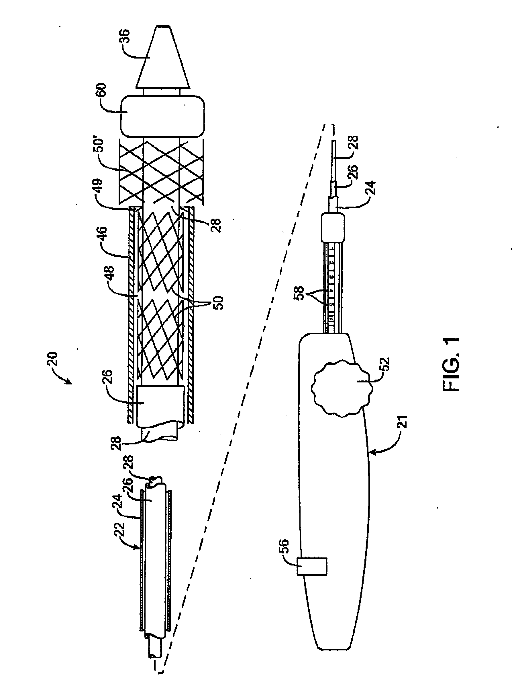
[0025] Referring to FIG. 1, a first embodiment of a prosthesis delivery catheter 20 according to the invention is illustrated. Delivery catheter 20 may have any of various constructions, including those described in co-pending U.S. patent application Ser. Nos. 10 / 637,713, (Attorney Docket No. 021629-000340US), filed Aug. 8, 2003; Ser. No. 10 / 874,859 (Attorney Docket No. 021629-000350US), filed Jun. 22, 2004; and Ser. No. 10 / 884,616, (Attorney Docket No. 021629-000360US), filed Jul. 2, 2004, all of which are hereby incorporated by reference. Delivery catheter 20 has a handle assembly 21 and an elongated catheter body 22 that includes three concentric tubular shafts, all axially slidable relative to one another: an outer shaft 24, a pusher 26, and an inner shaft 28. A distal portion of delivery catheter 20 is shown schematically and in partial cutaway view for clarity. The distal portion, as well as other portions of delivery catheter 20 may include additional features not shown. For ...


PUM


Abstract

Custom-length self-expanding stent delivery systems and methods enable precise control of prosthesis position during deployment. The stent delivery systems carry multiple stent segments and include a stent bumper for helping control the axial position of the stent segments during deployment. This enables the deployment of multiple prostheses at a target site with precision and predictability, preventing stent segment recoil and ejection from the delivery device and thus eliminating excessive spacing or overlap between prostheses. In particular embodiments, the prostheses of the invention are deployed in stenotic lesions in coronary or peripheral arteries or in other vascular locations.

Description

CROSS REFERENCE TO RELATED APPLICATIONS [0001] This application is a continuation-in-part of U.S. patent application Ser. No. 10 / 879,949 (Attorney Docket No. 021629-002700US), filed Jun. 28, 2004, which is hereby incorporated fully by reference.BACKGROUND OF THE INVENTION [0002] Stents are tubular prostheses designed for implantation in a vessel to maintain patency of the vessel lumen. Stents are used in various vessels throughout the body, including the coronary arteries, femoral arteries, iliac arteries, renal artery, carotid artery, vascular grafts, biliary ducts, trachea, and urethra. Stents are typically implanted by means of long, flexible delivery catheters that carry the stents in a compact, collapsed shape to the treatment site and then deploy the stents into the vessel. In some applications, balloon expandable stents are used. These stents are made of a malleable metal such as stainless steel or cobalt chromium and are expanded by means of a balloon on the tip of the deliv...

Claims


Application Information

Patent Timeline
Patent Type & Authority Applications(United States)
IPC IPC(8): A61F2/82A61F2/84
CPCA61F2/95A61F2/958A61F2/966A61F2/97A61F2002/9665A61F2002/9505A61F2002/9511A61F2002/9583A61F2002/826
Inventor ANDREAS, BERNARDGRAINGER, JEFFRY J.
Owner JW MEDICAL SYSTEMS LTD
Why Eureka
Try Eureka