Endoscopic beating-heart stabilizer and vessel occlusion fastener

a technology of endoscopic beating and heart valve, applied in the field of surgical, can solve the problems of coronary artery disease, a leading cause of morbidity and mortality, and the use of cpb in conventional cabg procedures, and achieve the effect of stabilizing the tissue and reducing the physiological motion of the stabilized region

Inactive Publication Date: 2007-07-31
INTUITIVE SURGICAL OPERATIONS INC
View PDF51 Cites 203 Cited by
  • Summary
  • Abstract
  • Description
  • Claims
  • Application Information

AI Technical Summary

Benefits of technology

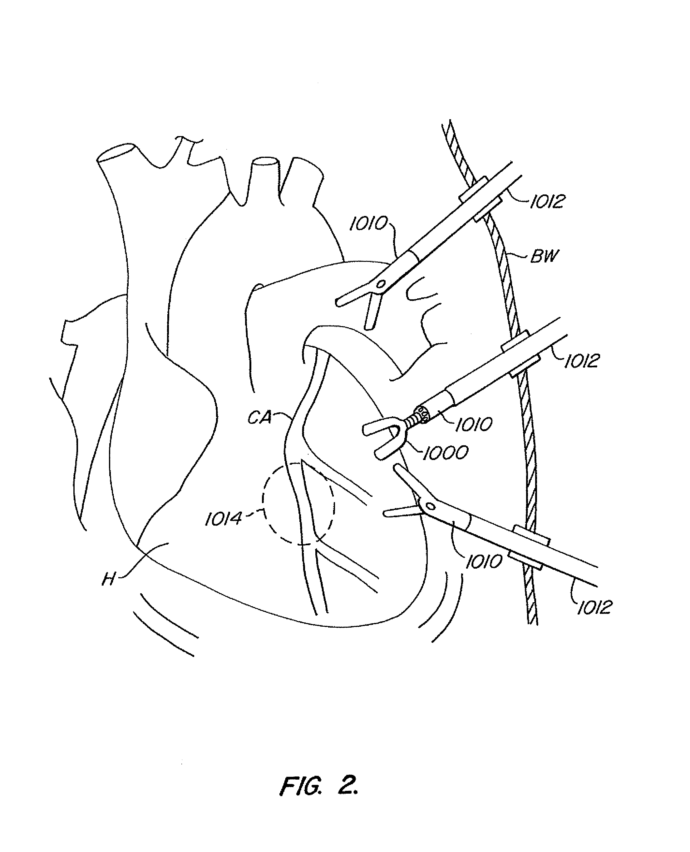
[0022]In a first aspect of the present invention, the stabilizer comprises an elongate shaft sized to allow insertion through an endoscopic cannula and a manipulable foot connected with the shaft. The foot is used to engage a target tissue, such as a portion of a beating heart, for stabilization. The stabilizer can inhibit (i.e., substantially reduce) physiological motion of the stabilized region without having to stop the heart. While the stabilized region will not necessarily be absolutely still, motion of the target tissues can be inhibited sufficiently to treat the target tissues, particularly with robotic surgical tools which move in response to inputs of a robotic system operator.
[0023]In some embodiments, the manipulable foot comprises a first toe portion rotateably joined

Problems solved by technology

Coronary artery disease remains a leading cause of morbidity and mortality, and particularly in industrialized societies.
One drawback of conventional CABG procedures is the use of CPB.
The use of CPB has been associated with an increased rate of stroke and neurological deficit.
However, the grafting and anastomosis procedure is often more challenging on a beating heart than on a heart that has been stopped by cardioplegia.
While elimination of CPB may improve the outcomes of many patients, the use of open-heart surgery to perform CABG is still highly traumatic to the patient.
Unfortunately, both the pro

Method used


Image

  • Endoscopic beating-heart stabilizer and vessel occlusion fastener
  • Endoscopic beating-heart stabilizer and vessel occlusion fastener
  • Endoscopic beating-heart stabilizer and vessel occlusion fastener

Examples


embodiment # 1

Additional Embodiment #1

[0146]FIG. 23 illustrates a first additional embodiment of the stabilizer. FIG. 23 provides a perspective over-all view of the stabilizer 15, which includes the elongate shaft 16 and stabilizer distal portion or foot 17. Again, the foot 17 comprises the jointed portion or ankle 18 connected with the pair of stabilizer bodies or toe portions 19. Also, the toe portions 19 are actuated and locked in a selected deployment position by the tension cable 20. Each toe 19 in turn mounts on of a pair of stabilizing surface or tissue engaging members 22, 22.

[0147]In this embodiment, the stabilizer 15 includes an adjustable cable tensioner 23, which comprises an internally threaded manual knob 24 engaging an externally threaded proximal cable junction 26. The knob 24 bears on a thrust bearing 28 which is mounted to the base of a proximal shaft housing 30. The cable 20 may be adjustably tensioned by turning the knob 24 to retract cable 20 until a selected tension is reach...

embodiment # 2

Additional Embodiment #2

[0165]FIG. 30 illustrates a second additional embodiment of the stabilizer. FIG. 30 is a perspective view showing the distal end of shaft 91 of the stabilizer 90. An attached foot portion 92 is comprised of stabilizing surfaces 93, 93′ which are supported by toe portions 94, 94′, respectively. The toe portions 94, 94′ are joined by a split ball mounting 96 which functions in a manner similar to the spherical split ball shell 1041, 1048 previously described. The split ball mounting 96 allows the toe portions 94, 94′ to rotate from the furled or stowed configuration to an open or deployed configuration. The shaft 91 rigidly connects to a joint socket housing 98 which encloses and mounts split ball 96 at its distal end. FIG. 31 is a top view of the stabilizer 90 distal end and FIG. 32 is a side view of the stabilizer 90 distal end.

[0166]FIG. 33 shows stabilizer 90 with the toe portions 94, 94′ and the stabilizing surfaces 93, 93′ rotated outwards by the split ba...

embodiment # 3

Additional Embodiment #3

[0171]FIG. 37 is a section plan view of an additional embodiment of a foot 130 of the stabilizer. As shown in this embodiment, the foot 130 comprises an ankle 18 and toes 19. The ankle 18 comprises a series of balls 36 and intermediate socket rings 37, of which only one is shown, connected with a housing 2000. Seals 2002 may be present between the balls 36 and socket rings 37 and between the ball 36 and housing 2000. The cable 20 enters the housing 2000 and connects with the toes 19 by connector cables 21. The cable 20 and connector cables 21 are joined with a cable crimp 2002. A push rod 2004 is disposed within each toe 19 and is engageable with a diamond dust ball link 2006. Each link 2006 is attached to a stabilizing surface or tissue engaging member 22. In addition, a vacuum or irrigation line 2008 is disposed within each toe 19 as shown. The principles of function and construction are generally similar to the Additional Embodiment #1.


PUM


Abstract

Devices, systems and methods related to endoscopic surgery, particularly related to robotic surgical operations, provide a tissue stabilizer for endoscopically stabilizing a target tissue within a patient's body. For stabilizing a beating heart during a closed-chest coronary artery bypass grafting procedure, a stabilizer is inserted through an endoscopic cannula and provides sufficient surface area to contact the heart and effectively stabilize the target tissue area. The stabilizer can straddle a blood vessel, such as a coronary artery, which is targeted for an anastomosis. Vessel occlusion fasteners may occlude the target blood vessel prior to the anastomosis procedure.

Description

CROSS-REFERENCES TO RELATED APPLICATIONS[0001]The present application also claims the benefit of priority from the following U.S. patent applications:[0002]No. 60 / 290,556, filed May 10, 2001, for “Endoscopic Beating-Heart Stabilizer Including Adjustable Irrigator and Vessel Occlusion Fastener”[0003]No. 60 / 285,641, filed Apr. 19, 2001, for “Endoscopic Beating-Heart Stabilizer”[0004]No. 60 / 253,484, filed Nov. 28, 2000, for “Endoscopic Beating-Heart Stabilizer”[0005]And the present application is a continuation-in-part and claims the benefit of priority from Ser. No. 09 / 436,524, filed Nov. 9, 1999, for “Stabilizer for Robotic Beating-Heart Surgery”, now issued as U.S. Pat. No. 6,398,726;[0006]The full disclosures of each of the above referenced patent applications are incorporated herein by reference.STATEMENT AS TO RIGHTS TO INVENTIONS MADE UNDER FEDERALLY SPONSORED RESEARCH OR DEVELOPMENT[0007]Not ApplicableREFERENCE TO A “SEQUENCE LISTING,” A TABLE, OR A COMPUTER PROGRAM LISTING APP...

Claims


Application Information

Patent Timeline
IPC IPC(8): A61B19/00A61B17/00A61B17/04A61B17/02A61B17/12A61B17/28A61B17/30
CPCA61B17/00234A61B17/1327A61B19/2203A61B17/122A61B17/0401A61B17/0469A61B17/0487A61B17/12013A61B19/26A61B19/5212A61B2017/00243A61B2017/0243A61B2017/0404A61B2017/0414A61B2017/0454A61B2017/0464A61B2017/2905A61B2017/2932A61B2017/2933A61B2017/306A61B2019/2223A61B2019/223A61B2019/2242A61B2019/2276A61B17/04A61B2034/742A61B34/71A61B90/361A61B90/50A61B34/30A61B34/37A61B34/35
Inventor JULIAN, CHRISTOPHER A.IKEDA, MICHAELRAMANS, ANDRIS D.HOORNAERT, DEAN F.ISAAC, MARGARET M.
Owner INTUITIVE SURGICAL OPERATIONS INC
Why Eureka
Try Eureka