Surgical instrumentation kit for inserting an ankle prosthesis

a technology for surgical instruments and prostheses, applied in the field of surgical instruments for inserting prostheses, can solve the problems of affecting the relative stability of the implanted bone, the inability to meet the needs of patients, and the short term of the stationary connection zone between the implant and the skid, so as to avoid any disturbance to the relative

Active Publication Date: 2007-07-26
SMITH & NEPHEW INC
View PDF65 Cites 61 Cited by
  • Summary
  • Abstract
  • Description
  • Claims
  • Application Information

AI Technical Summary

Benefits of technology

[0026] Advantageously, the joint surfaces of the talus phantom and of the phantom skid adapted for co-operating with each other are complementary to each other in horizontal section. In this way, medio-lateral movement is limited or prevented between the phantom skid and the talus phantom during the preoperative movement of the phantom components in the ankle of the patient, thus avoiding any disturbance to the relative medio-lateral positioning between the bottom end of the tibia and the subassembly constituted by the phantom skid and the tibial phan...

Problems solved by technology

In spite of the structural qualities of ankle prostheses, clinical hindsight shows that such ankle prostheses are implanted quite frequently in unsatisfactory manner.
For example, for a stationary skid prosthesis, significant excess stress is to be observed in service between the skid and the tibial implant, which leads in the fairly short term to the stationary connection zone between the implant and the skid breaking, or to damage to the end of the tibial bone.
With regard to moving skid prostheses, which specifically tend to be used to overcome the above-mentioned drawback of stationary skid prostheses,...

Method used


Image

  • Surgical instrumentation kit for inserting an ankle prosthesis
  • Surgical instrumentation kit for inserting an ankle prosthesis
  • Surgical instrumentation kit for inserting an ankle prosthesis

Examples


Embodiment Construction

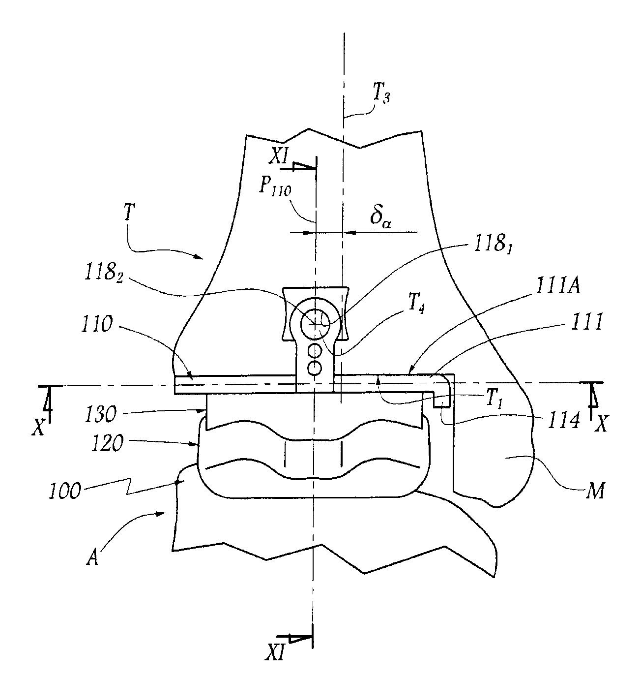
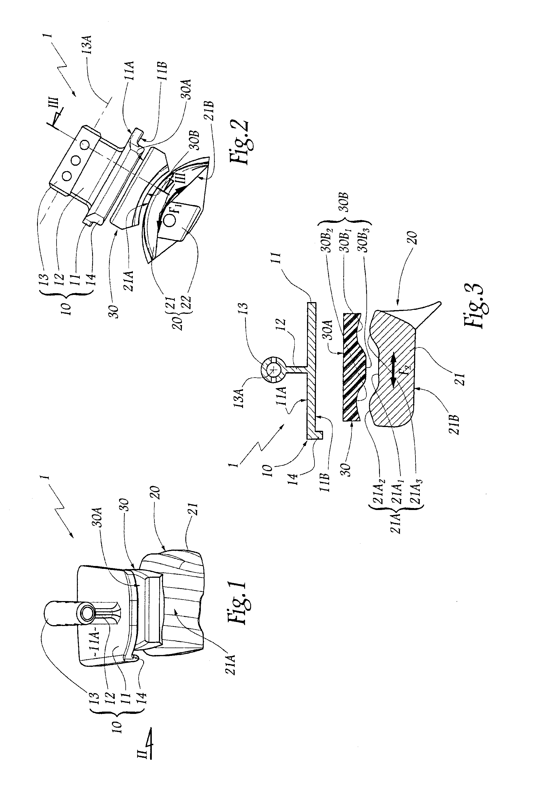
[0041] FIGS. 1 to 3 show an example of a “moving skid” ankle prosthesis. The prosthesis comprises three distinct components for implanting in the place of a right ankle joint of a human being, namely a tibial implant 10, a talus implant 20, and a prosthetic skid 30. For convenience, the description below describes directions relative to the bones of an ankle in their anatomical position, i.e. the terms “posterior” or “rear”, “anterior front”, “right”, “left”, “upper”, “lower”, etc. should be understood relative to the ankle of a patient standing on a substantially horizontal surface. Similarly, the term “sagittal” corresponds to a direction in the antero-posterior direction vertically on the mid-line of the ankle, while the term “medial” corresponds to a direction substantially perpendicular to the sagittal plane of the ankle, and directed towards the ankle, with the term “lateral” corresponding to the opposite direction.

[0042] The tibial implant 10 comprises a plate 11 for securin...


PUM


Abstract

A surgical instrument including at least one tibial phantom generally corresponding to at least certain features of the tibial implant. The tibial phantom includes a top surface adapted to move freely against the prepared bottom end of the tibia. At least one talus phantom generally corresponding to at least certain features of the talus implant is engaged with the prepared top surface of the talus. At least one phantom skid is located between the tibial phantom and the talus phantom. The phantom skid is engaged with the tibial phantom such that dynamic engagement between the phantom skid and the talus phantom through at least extension and flexion of the ankle joint positions the tibial phantom on the prepared bottom end of the tibia. The phantom skid can either be a part of the tibial phantom or a separate component.

Description

CROSS-REFERENCE TO RELATED APPLICATIONS [0001] The present application claims priority to prior French Application No. 0600644, filed Jan. 24, 2006, entitled Ensemble D'instrumentation Chirurgicale pour poser une prothese de Cheville. The present application also claims the benefit of U.S. Provisional Application No. 60 / 762,139 filed Jan. 26, 2006, entitled Ensemble D'instrumentation Chirurgicale pour poser une prothese de Cheville. The entire specification of both applications noted-above are hereby incorporated by reference.FIELD OF THE INVENTION [0002] The present invention relates to a surgical instrumentation kit and associated method for implanting an ankle prosthesis. BACKGROUND OF THE INVENTION [0003] An ankle prosthesis mainly includes a tibial implant, a talus implant, and a prosthetic skid interposed between the tibial and talus implants. The prosthetic skid is said to be “moving” when it is assembled to the tibial and talus implants so as to be movable relative to both o...

Claims


Application Information

Patent Timeline
IPC IPC(8): A61F2/42
CPCA61B17/15A61F2/4202A61F2/4606A61F2002/4628A61F2002/4622A61F2002/4623A61F2/4684A61F2/4603
Inventor RATRON, YVES-ALAINCARDON, JEAN-EMMANUELJUDET, THIERRYCOLOMBIER, JEAN-ALAINBONNIN, MICHEL
Owner SMITH & NEPHEW INC
Why Eureka
Try Eureka