
Application interface including dynamic transform definitions

a dynamic transformation and application interface technology, applied in the field of computer software, can solve problems such as transforms introducing a new potential error source, transforms requiring significant effort, and current transform methods suffering significant disadvantages, and achieve the effect of increasing the range of formats and data structures

Active Publication Date: 2007-07-26
ORACLE INT CORP
View PDF3 Cites 22 Cited by
  • Summary
  • Abstract
  • Description
  • Claims
  • Application Information

AI Technical Summary

Benefits of technology

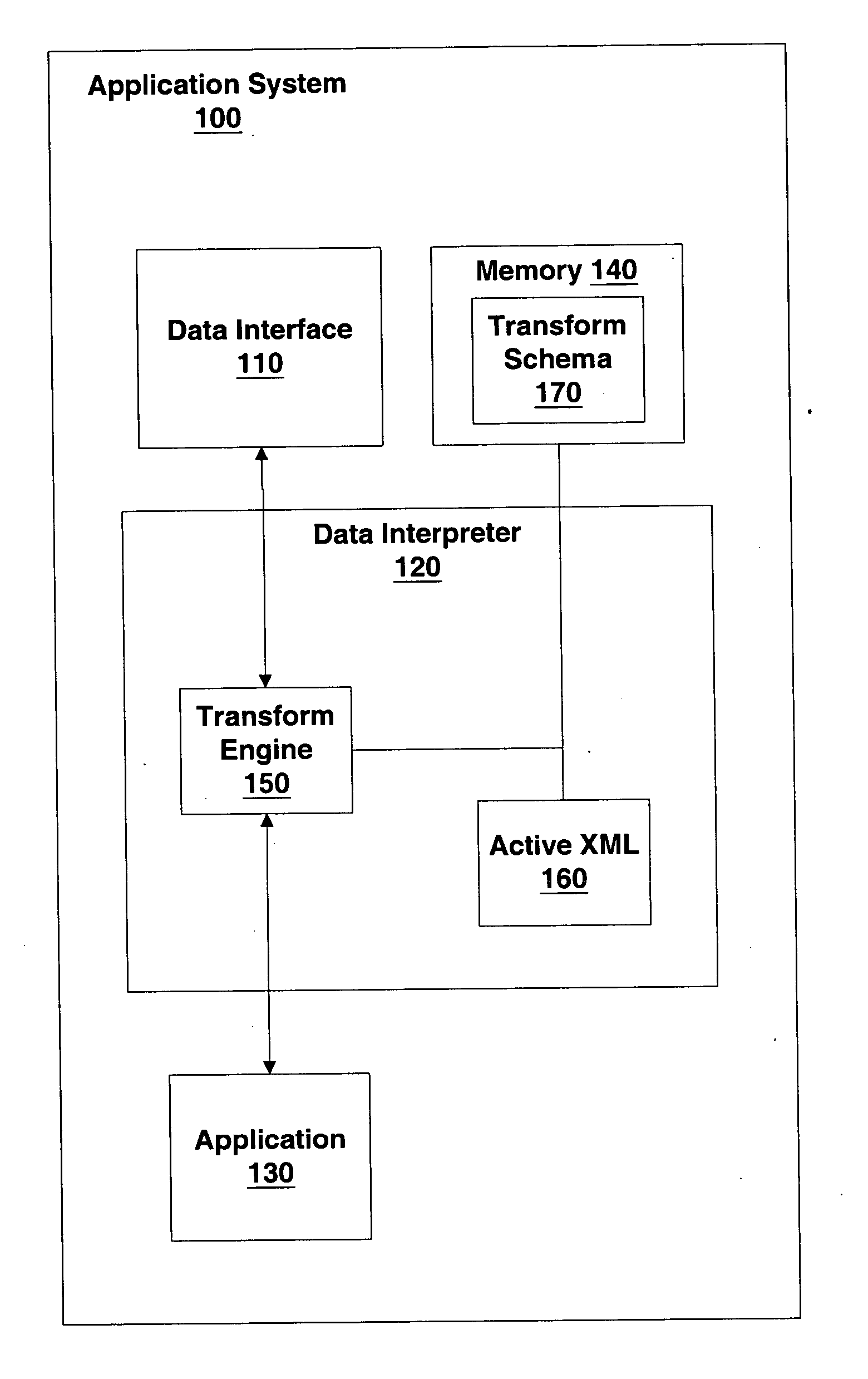
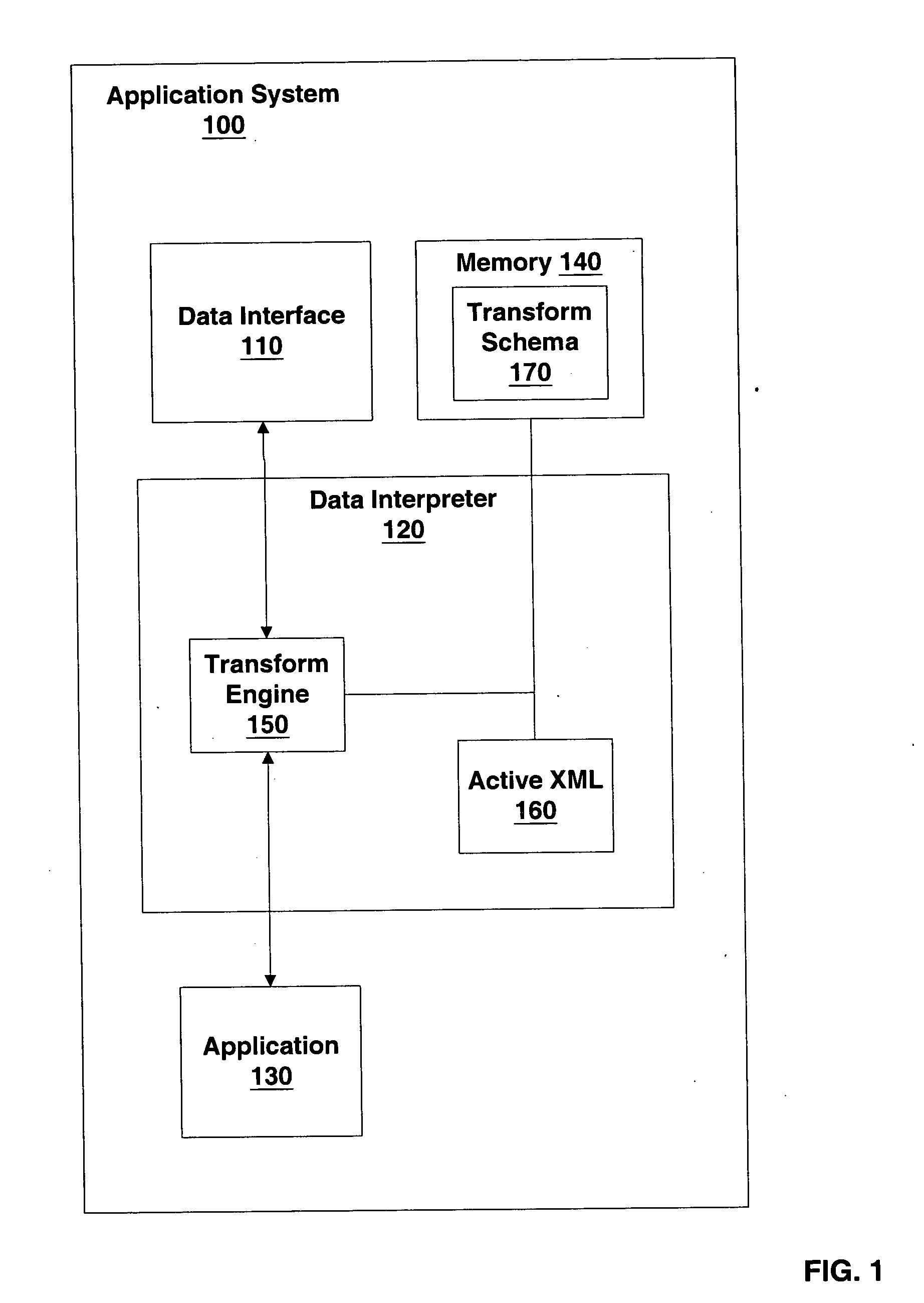
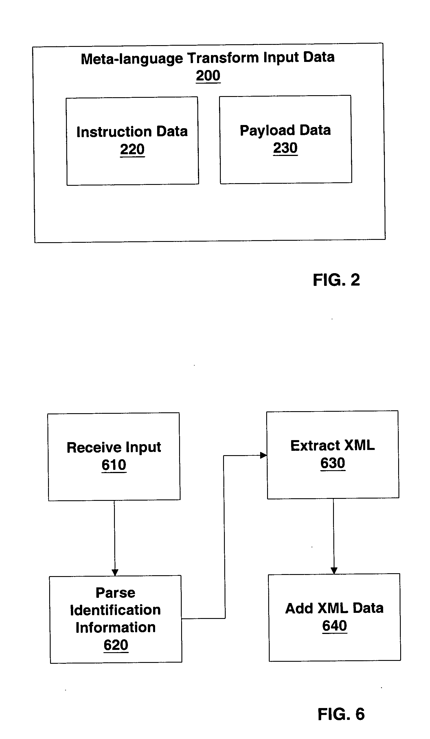
[0008] The invention includes systems and methods of transforming data communicated through an application programming interface. This data may include both commands configured to direct an application and parameters on which the application is configured to act. The transformation uses a transform schema (transform process definition) that dynamically directs the transform process as it is occurring, in addition to mapping input data fields to output data fields. Typically, the transform process definition is in the form of meta-language configured to be interpreted during the defined transformation. Through the systems and methods described herein, the versatility and ease-of-use associated with meta-languages may be imparted to application programming interfaces thus increasing the range of formats and data structures with which communication can occur.

Problems solved by technology

This process can require significant effort and often includes rewriting common sections of script.
However, even when taking advantage of metadata, current transform methods suffer significant disadvantages.
For example, transforms introduce a new potential source of error that can be difficult to debug.
They are, therefore not configurable to take advantage of dynamic multi-thread computing.
Further, this serial approach makes nesting and un-nesting operations difficult.
Even when the transform code is generated using a script, the transformation code is static at the time of execution and therefore not configurable for dynamic optimization of the transform process.

Method used


Image

  • Application interface including dynamic transform definitions
  • Application interface including dynamic transform definitions
  • Application interface including dynamic transform definitions

Examples


Embodiment Construction

[0029] The invention includes a data interpreter configured to interpret data stored in a variety of data structures. The data interpreter may be integrated into an application or alternatively be part of an application programming interface used by one or more associated applications. The data interpreter includes a transformation engine configured to transform data from one data structure to another under the control of a transform process definition. In some instances this transformation includes transforming received data into a format that can be directly read by a first application and in some instance this transformation includes transforming output data of the first application to a format intended for a second application.

[0030] The transformation process performed by the transformation engine is defined and controlled by a structured transform process definition. In typical embodiments, this transform process definition includes a hierarchical set of nested records defini...


PUM


Abstract

An application programming interface configured to transform data responsive to a transform process definition. The transform process definition is interpreted concurrently with the transformation process. This interpretation dynamically determines navigation within, and processing of, the data to be transformed. Under control of the transform process definition, a transform engine is configured to transform input data using recursive calls to a transformation process. The recursive approach is responsive to data structures within the transform process definition and simplifies operations such as parallel processing, load-balancing of transformation tasks, nesting, un-nesting, filtering, and the like.

Description

BACKGROUND [0001] 1. Field of the Invention [0002] The invention is in the field of computer software and more specifically in the field of application interfaces. [0003] 2. Description of the Prior Art [0004] Computing systems are benefited by their ability to exchange data between applications. In some cases, this ability is extended to allow one application to call functions within another application. For example, it is common for a word processing program to transfer data and execute functions of a printer driver. These functions are accessed using application programming interfaces (APIs) defined for the word processing program and the printer driver. [0005] When disparate applications must communicate with each other it is not unusual to transform data as part of the communication. This transform converts data from a format generated by one application to a format understood by the other application. In some cases scripts are used to generate transformation code that is then ...

Claims


Application Information

Patent Timeline
IPC IPC(8): G06F9/46G06F9/44G06F13/00G06F3/00G06F40/00
CPCG06F9/541G06F9/45508
Inventor SMIRNOV, DMITRY M.SCHROEDER, RALF
Owner ORACLE INT CORP
Learn More