
Apparatus for processing sensor signal from knock sensor of internal combustion engine

a technology for internal combustion engines and sensors, which is applied in mechanical devices, machines/engines, instruments, etc., can solve the problems of increasing the level of electrical noise within motor vehicles, significant problems, and increasing the electrical noise generated as a result of communication itself, so as to achieve the effect of reducing the overall time required for digital filter processing and slowing down the access speed

Inactive Publication Date: 2007-08-02
DENSO CORP
View PDF8 Cites 26 Cited by
  • Summary
  • Abstract
  • Description
  • Claims
  • Application Information

AI Technical Summary

Benefits of technology

The invention provides a knock sensor signal processing apparatus that reduces the amount of data transmitted between two devices while still maintaining the sampling period of the knock sensor signal. This is achieved by using a communication line consisting of a first set of communication lines for transmitting the A / D values from the first apparatus to the second apparatus and a second set of communication lines for transmitting information about operating commands from the second apparatus to the first apparatus. By increasing the number of communication lines in the first set of communication lines and transmitting the A / D values in a periodic manner, the amount of data transferred per unit time interval is increased without increasing the communication speed. This reduces the amount of electrical noise generated as a result of data communication. Additionally, the invention provides a fail-safe mode of operation that can be initiated in response to failure of a communication line.

Problems solved by technology

Furthermore in recent years there has been an increasing tendency for the level of electrical noise within a motor vehicle to increase, as the number of functions performed by equipment of vehicles continues to increase.
However if this is done, then the electrical noise that is generated as a result of the communication itself will be increased.
This is a significant problem.
Hence, the overall system scale would become excessive.

Method used


Image

  • Apparatus for processing sensor signal from knock sensor of internal combustion engine
  • Apparatus for processing sensor signal from knock sensor of internal combustion engine
  • Apparatus for processing sensor signal from knock sensor of internal combustion engine

Examples


first embodiment

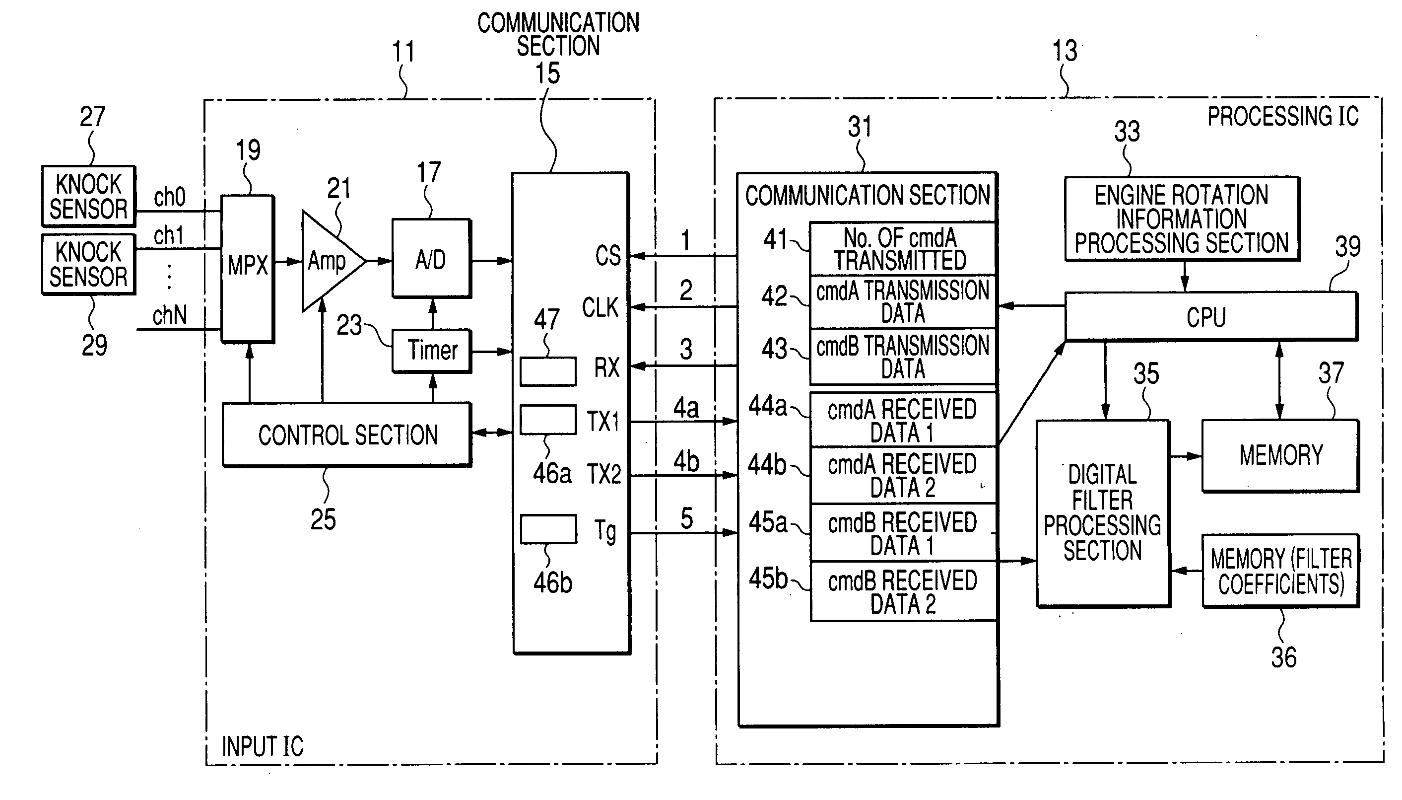
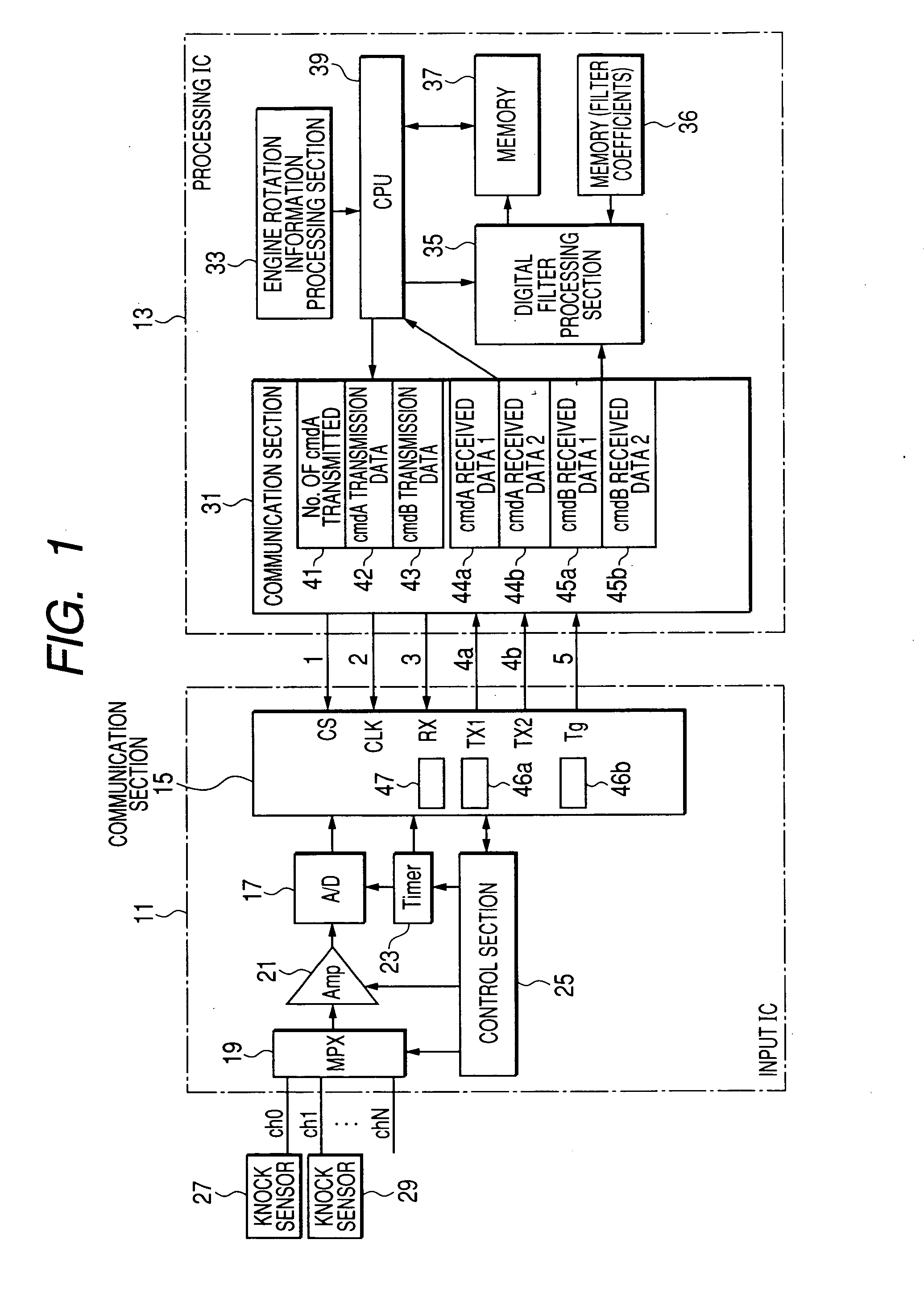
[0060]Referring to FIG. 1, the general circuit configuration of a first embodiment of a knock sensor signal processing apparatus is shown. With this embodiment, a first apparatus which performs A / D conversion of knock sensor signals and a second apparatus which performs digital signal processing of the resultant A / D values are respectively implemented as a input IC 11 and a processing IC 13. These are connected for serial communication via six communication lines 1 to 3, 4a, 4b and 5.

[0061]The input IC 11 includes a circuit referred to as the communication section 15, for performing communication with the processing IC 13, an A / D converter 17, and a multiplexer 19 which selects one of a plurality of input channels ch0 to chN and transfers an input analog signal via the selected channel to the input of an amplifier 21. The amplifier 21 amplifies that analog signal by a specific amount of gain, and inputs the resultant signal to the A / D converter 17. Although not shown in the drawings...

second embodiment

[0224]A second embodiment will be described, which differs from the above first embodiment only in that the CPU 39 of the processing IC 13 of the second embodiment performs processing shown in the flow diagram of FIG. 14, while the communication section 31 in the processing IC 13 of the second embodiment performs processing that is changed from that of FIGS. 6A, 6B to that of FIGS. 15A, 15B. The processing contents of step S327 of FIGS. 15A, 15B are shown in the flow diagram of FIG. 16.

[0225]With the second embodiment, the memory 36 has stored therein a first set of filter coefficients (A*1 to A*6) appropriate for use when the sampling period is 5 microseconds as for the first embodiment, with these filter coefficients being referred to in the following as the 5-microsecond filter coefficients, and also a second set of filter coefficients, which are appropriate for use when the sampling period is 10 microseconds, with these being referred to in the following as the 10-microsecond fi...

embodiment 1

Alternative Embodiment 1

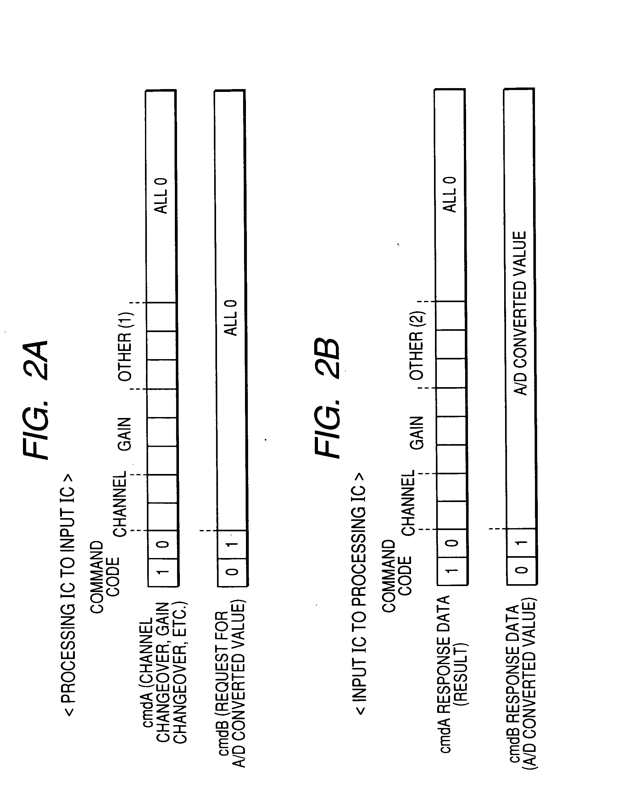
[0260]When the communication lines 4a and 4b of the above embodiments are located close to one another, there will be a possibility of a short-circuit occurring between them. With a first alternative embodiment, as shown in FIG. 17, when a pair of cmdA response data sets are transmitted from the input IC 11 to the processing IC 13 via the communication lines 4a, 4b respectively (i.e., TX1-side transmission and TX2-side transmission respectively), the two cmdA response data sets are distinguished from one another by being assigned respectively different orders of the bits in their command code, i.e., [10] and [01] in the example of FIG. 17. Similarly, when a pair of cmdB response data sets are transmitted from the input IC 11 to the processing IC 13 via the communication lines 4a, 4b respectively, the two cmdB response data sets are assigned respectively different orders of the bits in their command codes, i.e., [01] and [10] in the example of FIG. 17.

[0261]In...


PUM

PropertyMeasurementUnit
frequencyaaaaaaaaaa
frequencyaaaaaaaaaa
rotationaaaaaaaaaa

Abstract

In a knock sensor signal processing apparatus, a first apparatus which receives an engine knock sensor signal performs A / D conversions of the signal with a predetermined period and transmits successive pluralities of A / D values in parallel, by serial data communication, to a second apparatus in response to respective commands received from the second apparatus. The number of communication lines provided for transmitting the A / D values is made greater than those for transmitting commands from the second apparatus to the first apparatus, so that a high A / D conversion frequency together with low data rate of transmitting the A / D values can be achieved, thereby reducing communication-generated noise.

Description

CROSS-REFERENCE TO RELATED APPLICATIONS[0001]This application is based on and incorporates herein by reference Japanese Patent Application No. 2006-019270 filed on Jan. 27, 2006.BACKGROUND OF THE INVENTION[0002]1. Field of Application[0003]The present invention relates to a knock sensor signal processing apparatus which performs A / D (analog-to-digital) conversion and digital filter processing of respective sensor signals produced from one or more knock sensors of an internal combustion engine.[0004]2. Description of Related Art[0005]Types of apparatus are known for use in controlling the engine of a vehicle whereby during each of successive intervals, a judgement is made as to whether knocking is occurring in a cylinder of the engine. The judgement is based upon an analog signal (referred to in the following as a knock sensor signal) produced from a knock sensor that is installed in the engine, with the knock sensor signal being subjected to A / D conversion at fixed periodic interval...

Claims


Application Information

Patent Timeline
Patent Type & Authority Applications(United States)
IPC IPC(8): G01L23/22G01R31/00
CPCG01L23/225
Inventor HONDA, TAKAYOSHI
Owner DENSO CORP
Learn More