Motor vehicle lock

a technology for motor vehicles and locks, applied in passenger lock actuation, lock applications, mechanical devices, etc., can solve the problems of increased force expenditure, increased ratchet and vehicle door raising, and complex construction, and achieve the effect of reducing construction effor

Inactive Publication Date: 2007-08-02
BROSE SCHLIESSSYSTEME GMBH & CO KG
View PDF6 Cites 2 Cited by
  • Summary
  • Abstract
  • Description
  • Claims
  • Application Information

AI Technical Summary

Benefits of technology

[0012] A primary object of the present invention is to embody and develop the known motor vehicle lock such that, with minimum construction effort, locking of the motor vehicle lock is also possible via the inside door handle.
[0014] The consideration of equipping the central locking lever in addition with a locking contour via which the central locking lever can be moved out of the unlocking position into the locking position by actuating the inside actuating lever in the locking direction which is opposite the opening direction is important. The inside actuating lever is therefore coupled to the central locking lever via the unlocking contour, on the one hand, and the locking contour, on the other. With a corresponding design, it can be ensured that the central locking lever hinders the actuation of the inside actuating lever in the opening direction as little as possible, such that the actuation of the inside actuating lever in the opening direction is therefore associated with minimum force expenditure.
[0016] In another preferred configuration, the inside actuating lever can be kept in the initial position or in the locking position by way of the locking contour or the unlocking contour. In this way, it is no longer necessary to assign a bi-stable leg spring to the inside actuating lever for the initial position, on the one hand, and the activation position, on the other.
[0019] Another preferred configuration relates to coupling of the inside door handle to the inside actuating lever by way of a “push-pull” Bowden cable, the use of which enables a simple, and at the same time, compact configuration. The aforementioned coupling of the central locking lever with the inside actuating lever can be provided between these two levers, or indirectly by way of the Bowden cable coupled to the inside actuating lever, especially the end piece of the core of the Bowden cable which faces the inside actuating lever.

Problems solved by technology

Finally, the actuation of the inside actuating lever causes raising of the ratchet and opening of the vehicle door.
The disadvantage is that manual locking of the motor vehicle lock, therefore manual movement of the central locking lever into the locking position, is associated with major construction effort.
This is also called “push-pull actuation.” The disadvantage in this concept is the fact that the raising of the ratchet is associated by the actuation of the inside actuating lever with tensioning of the spring, therefore with increased expenditure of force, and furthermore, that the construction is complex.
The arrangement is such that the pivoting range of the inside actuating lever is limited by the continuing coupling between the inside actuating lever and the central locking lever.
This can be disadvantageous in certain applications.
Here, the inside actuating lever is, to a certain extent, motion-coupled to the central locking lever, by which major construction limitations arise.

Method used


Image

  • Motor vehicle lock
  • Motor vehicle lock
  • Motor vehicle lock

Examples


Embodiment Construction

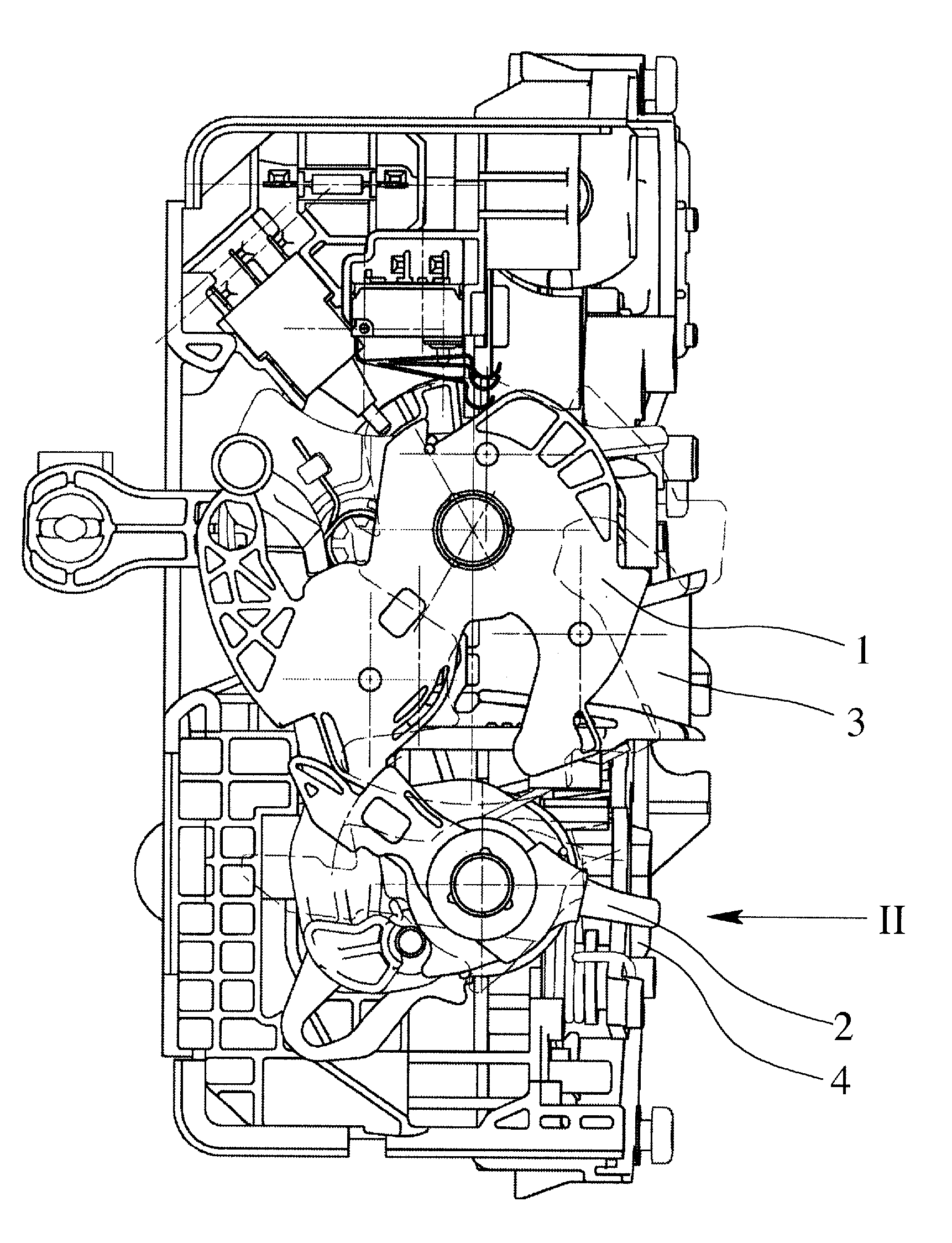
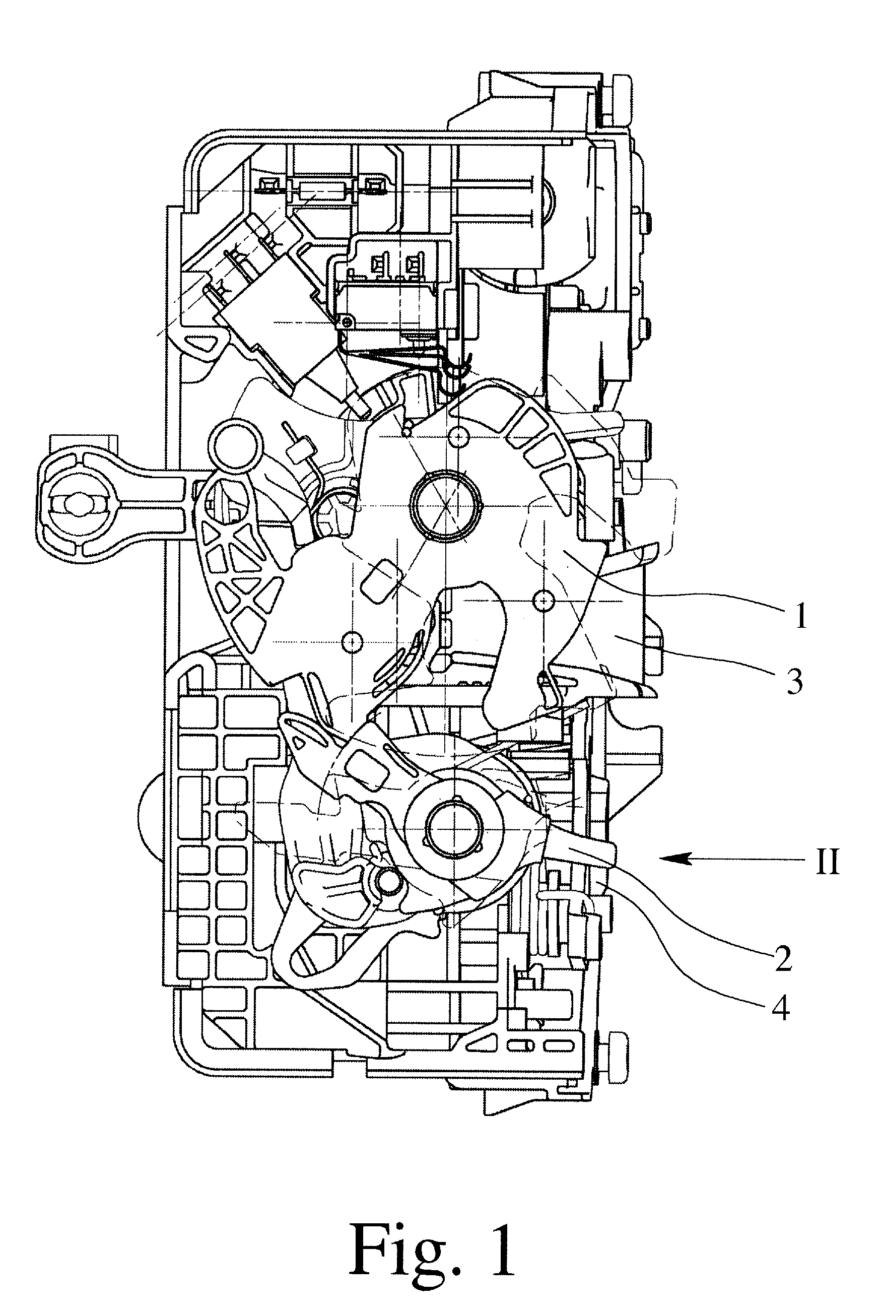
[0026] The vehicle lock shown in FIG. 1 shows the conventional latching elements latch 1 and ratchet 2 which are located in a housing. The housing has an inlet slot 3 via which a striker (not shown), and which is generally located on the body of the vehicle, engages the latch 1 when the vehicle door is shut. In FIG. 1, the ratchet 1 engages the latch 1 with blocking; this corresponds to the closed state of the vehicle door.

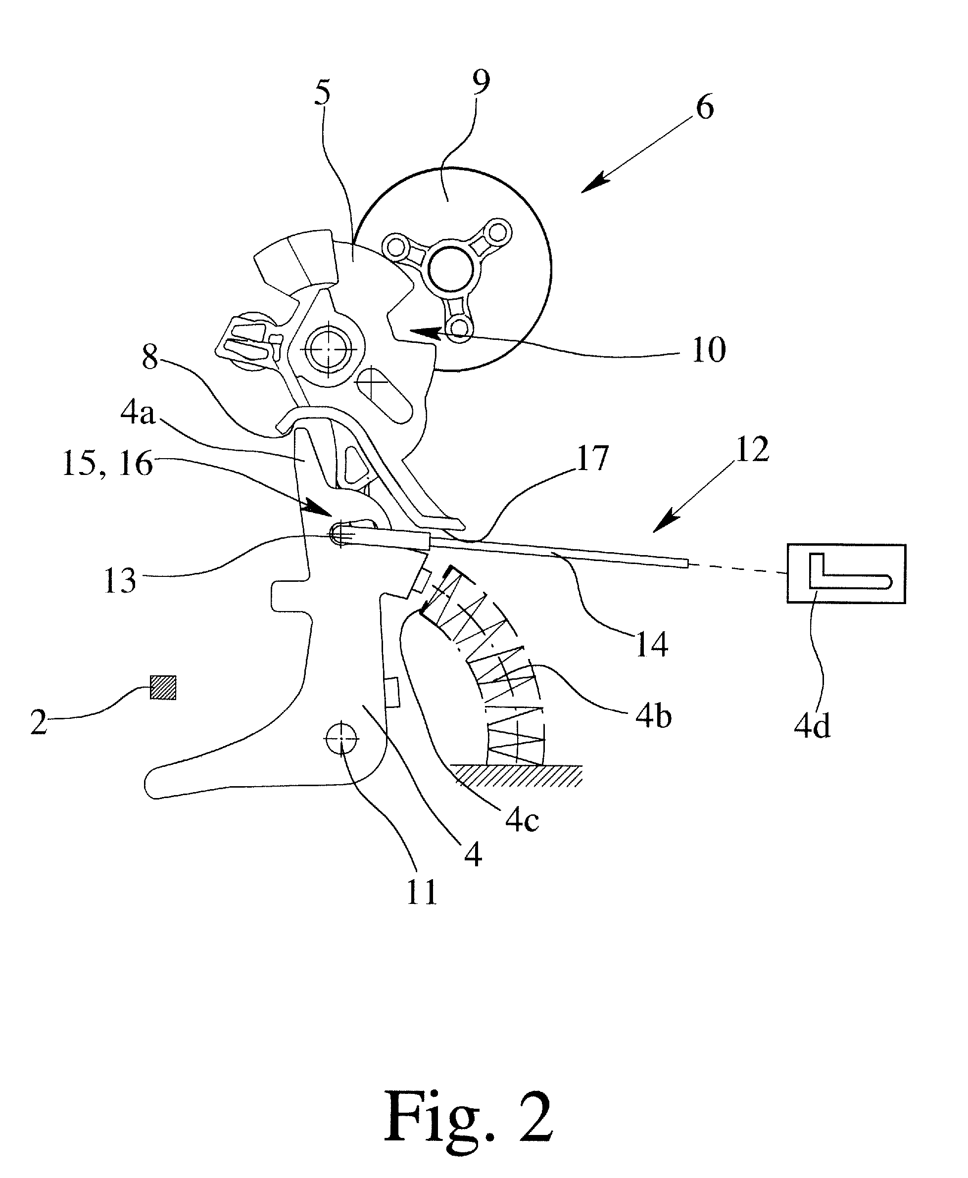
[0027]FIG. 2 shows part of the lock mechanism of the vehicle lock which is used for controlled actuation of the ratchet 2, which is shown here in a section. The lock mechanism is equipped with an inside actuating lever 4 which can be actuated from the inside door handle 4d. Furthermore, there is a central locking lever 5 which couples an outside door handle which is likewise not shown to the ratchet 2 or decouples it from the latter.

[0028] The central locking lever 5 can be moved by motor by the central locking drive 6 into an unlocking position which couples th...


PUM


Abstract

To embody and develop a known motor vehicle lock such that, with minimum construction effort, locking of the motor vehicle lock is also possible via the inside door handle, the central locking lever has, in addition to an unlocking contour that, by actuating the inside actuating lever in an opening direction and with the central locking lever in the locking position, is engaged by the inside actuating lever so as to transfer the central locking lever into the unlocking position and then disengages from the unlocking contour, is additionally provided with a locking contour via which the central locking lever is movable from the unlocking position into the locking position by actuating the inside actuating lever in a locking direction which is opposite the opening direction.

Description

BACKGROUND OF THE INVENTION [0001] 1. Field of the Invention [0002] This invention relates to a motor vehicle lock with latching elements, such a latch and a ratchet, and with a lock mechanism for controlled actuation of the ratchet, the lock mechanism having an inside actuating lever which can be actuated from the inside door handle and a central locking lever which couples and decouples an outside door handle with the ratchet, the central locking lever being moved by a motor of a central locking drive into an unlocking position which couples the outside door handle to the ratchet and into a locking position which decouples the outside door handle, the central locking lever having an unlocking contour that, by actuating the inside actuating lever in the opening direction and with the central locking lever in the locking position, the inside actuating lever first engages the unlocking contour of the central locking lever, and in doing so, transfers the central locking lever into the...

Claims


Application Information

Patent Timeline
Patent Type & Authority Applications(United States)
IPC IPC(8): E05C3/06
CPCE05B77/30E05B79/20E05B81/16E05B81/06Y10T292/1047
Inventor JOSCHKO, ROMANHAGER, OLEBROSE, SIMON
Owner BROSE SCHLIESSSYSTEME GMBH & CO KG
Why Eureka
Try Eureka