
Electromagnetic actuator for a surgical instrument and method for setting a stroke distance

Active Publication Date: 2015-10-08
OLYMPUS WINTER & IBE
View PDF11 Cites 4 Cited by
  • Summary
  • Abstract
  • Description
  • Claims
  • Application Information

AI Technical Summary

Benefits of technology

The patent text describes an electromagnetic actuator for a medical instrument that can compensate for optical system errors with minimal effort and simplify the setting of the stroke distance. The actuator has a fixed angular relationship between the stator and the movable element, which reduces energy consumption. The pole shoes have aligned regions that minimize the gap between them, allowing for rotational coupling over the entire length of the stator and avoiding torsions. The actuator can have two permanent magnets with a coil for generating switchable magnetic fields. The technical effects of the patent text are improved accuracy and efficiency of the actuator for medical instruments.

Problems solved by technology

Due to repeated translatory movement or external influences such as vibrations or assembly forces, it is possible that the optical system is no longer in optimal focus.
This can occur after the installation or after multiple actuations of the actuator, for instance due to manufacturing defects in the components or also positioning and alignment errors during the assembly, wherein a rotational movement of the traveller can occur.
If subsequent changes to the optical system occur, this can negatively influence the reproduced image quality.
Still further with such actuators, the setting of the stroke distance with the assembly is very complex.
The disadvantages of the prior art are overcome in that the angular relationship of the stator and traveller, or respectively the movable element, are fixed to each other by means of the structured surfaces of the pole shoes.
Now, a loss of adjustment can no longer occur since the traveller, or respectively the movable element, rotates in the stator due to multiple switching, and thus leading to a deviation from the optimized arrangement with the assembly.
Thus, it is not necessary to use a mechanical guide for the rotational position, which is complex depending on construction and is associated with an additional increase of the friction in the system.

Method used


Image

  • Electromagnetic actuator for a surgical instrument and method for setting a stroke distance
  • Electromagnetic actuator for a surgical instrument and method for setting a stroke distance
  • Electromagnetic actuator for a surgical instrument and method for setting a stroke distance

Examples


Embodiment Construction

[0036]In the drawings, the same or similar elements and / or parts are provided with the same reference numbers in order to prevent the item from needing to be reintroduced.

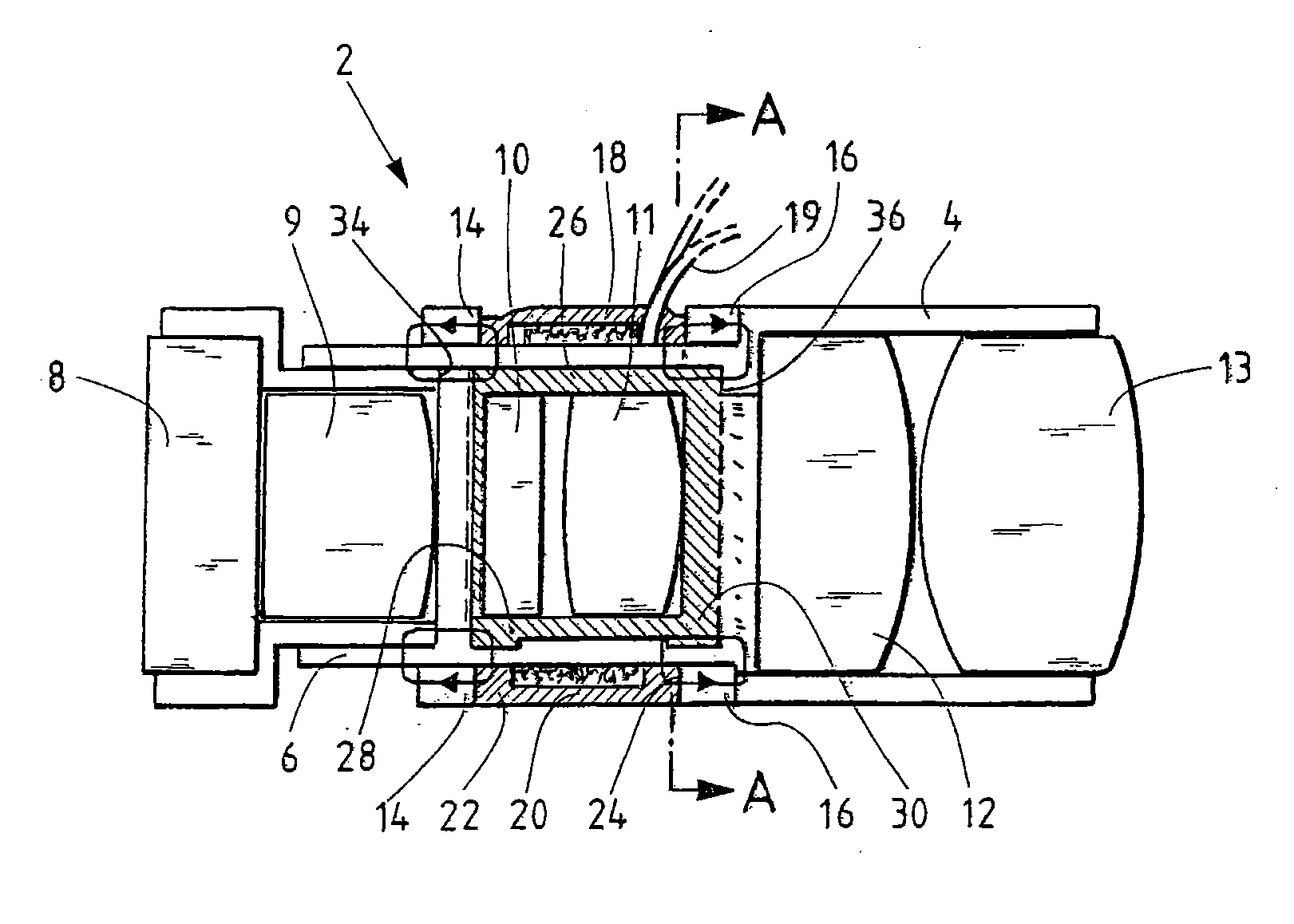
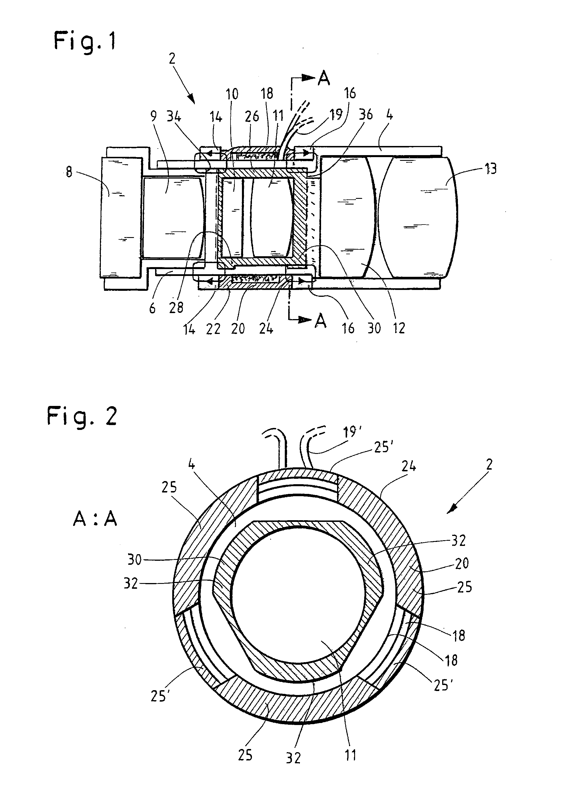
[0037]In FIG. 1, a sliding tube 4, in which lenses 12, 13 are arranged in a lens arrangement, can be seen in a schematic longitudinal section through an actuator 2. A lens holder 6 is arranged distally in the inner sliding tube 4 for distal input lenses 8, 9 of the lens arrangement, wherein the lens holder 6 is securely connected to the sliding tube 4.

[0038]Between the lenses 8, 9 and 12, 13 two further lenses 10, 11 of the lens arrangement are represented that are enclosed in an enclosure made of soft magnetic material, which has in each case, at its proximal and distal end, a distal pole shoe 28, or respectively a proximal pole shoe 30. This enclosure forms the traveller of the actuator 2. As seen in the lower region of FIG. 1, the pole shoes 28, 30 are structured in the radial direction along the circumference.

[...


PUM


Abstract

An electromagnetic actuator for a medical instrument including: a stator; and a movable element, at least partly composed of a paramagnetic and / or a ferromagnetic material, and which can be reversibly moved from a first to a second position by the application of a switchable magnetic field, wherein the stator and the movable element have annular distal and proximal pole shoes corresponding to each other, wherein the distal pole shoes and / or the proximal pole shoes of the stator and the movable element are aligned with each other in an overlapping manner in the first and / or the second position, and the distal pole shoes and / or the proximal pole shoes of the stator and the movable element have a structure in the circumferential direction on the surfaces of pole shoes facing each other, with the structures corresponding to each other.

Description

CROSS-REFERENCE TO RELATED APPLICATION[0001]The present application is a continuation of PCT / EP2013 / 003609 filed on Nov. 29, 2013, which is based upon and claims the benefit to DE 10 2012 224 177.9 filed on Dec. 21, 2012, the entire contents of each of which are incorporated herein by reference.BACKGROUND[0002]1. Field[0003]The present application relates to an electromagnetic actuator for a surgical or medical instrument, wherein the actuator comprises a stator and a movable element, which is at least partly composed of a paramagnetic and / or ferromagnetic material and which can be reversibly moved from a first position to a second position by the application of a switchable magnetic field, wherein the stator and the movable element have annular distal and proximal pole shoes that correspond to each other, wherein the distal pole shoes and / or the proximal pole shoes of the stator and the movable element are aligned with each other in an overlapping manner in the first position and / o...

Claims


Application Information

Patent Timeline
IPC IPC(8): H01F7/08H01F7/122A61B17/00H01F7/16
CPCH01F7/081H01F7/1607A61B2017/00398A61B17/00A61B2017/00876H01F7/122A61B1/00183A61B1/00188G02B7/102G02B23/2407H01F7/1615H02K33/00A61B1/0011
Inventor WIETERS, MARTINNOACK, ANDREAS
Owner OLYMPUS WINTER & IBE
Learn More