Apparatus on a textile machine for cleaning fibre material, for example of cotton, comprising a high-speed first or main roller

a textile machine and textile material technology, applied in the field of textile machine apparatus, can solve the problem that fibres are able to penetrate only unsatisfactory into the bottom of clothing, and achieve the effect of considerably increasing the degree of cleaning

Inactive Publication Date: 2007-08-09
TRUETZSCHLER GMBH & CO KG
View PDF9 Cites 33 Cited by
  • Summary
  • Abstract
  • Description
  • Claims
  • Application Information

AI Technical Summary

Benefits of technology

[0005]It is an aim of the invention to provide an apparatus

Problems solved by technology

The wire clothing has fine teeth, so that the fibres are able to

Method used


Image

  • Apparatus on a textile machine for cleaning fibre material, for example of cotton, comprising a high-speed first or main roller
  • Apparatus on a textile machine for cleaning fibre material, for example of cotton, comprising a high-speed first or main roller
  • Apparatus on a textile machine for cleaning fibre material, for example of cotton, comprising a high-speed first or main roller

Examples


Embodiment Construction

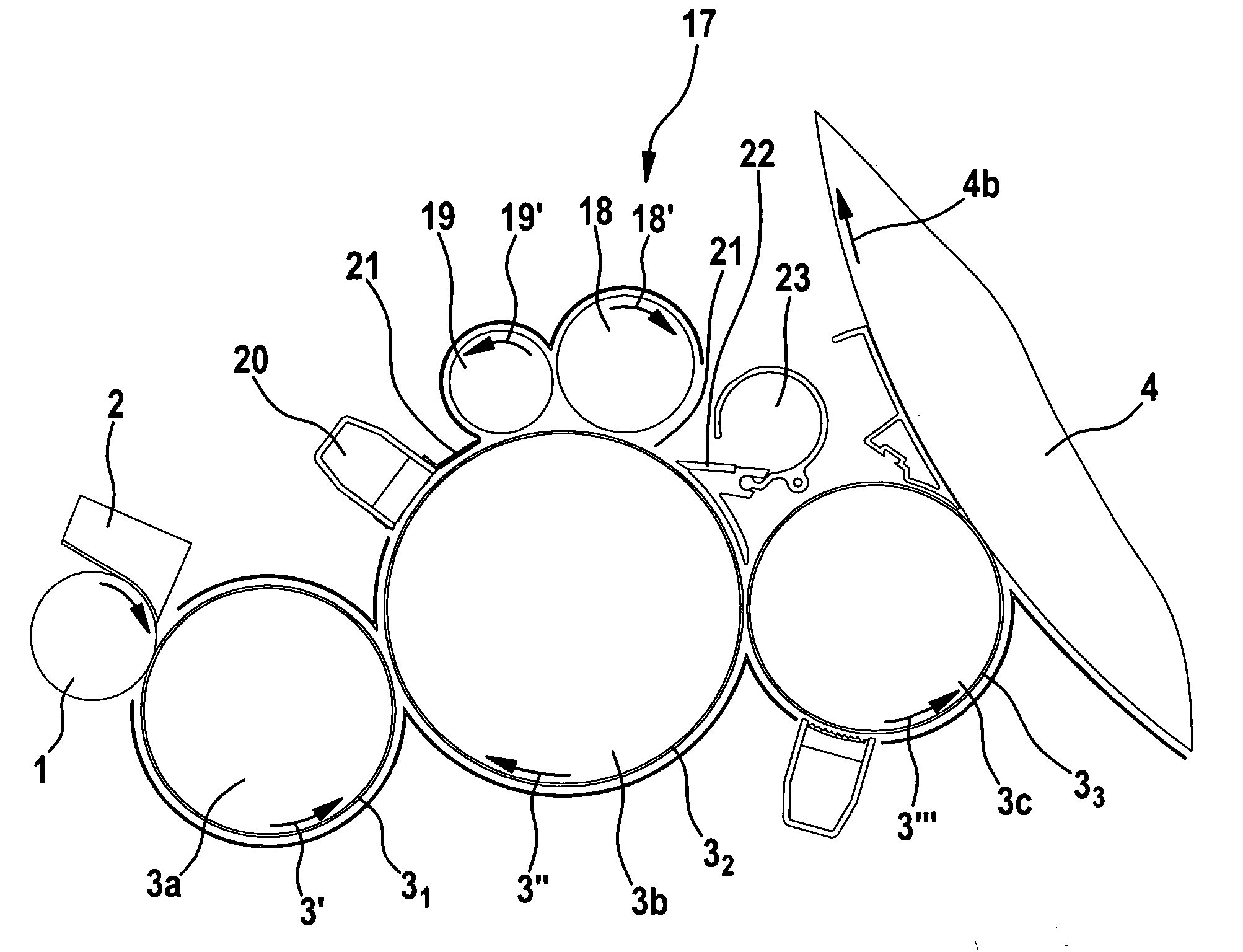
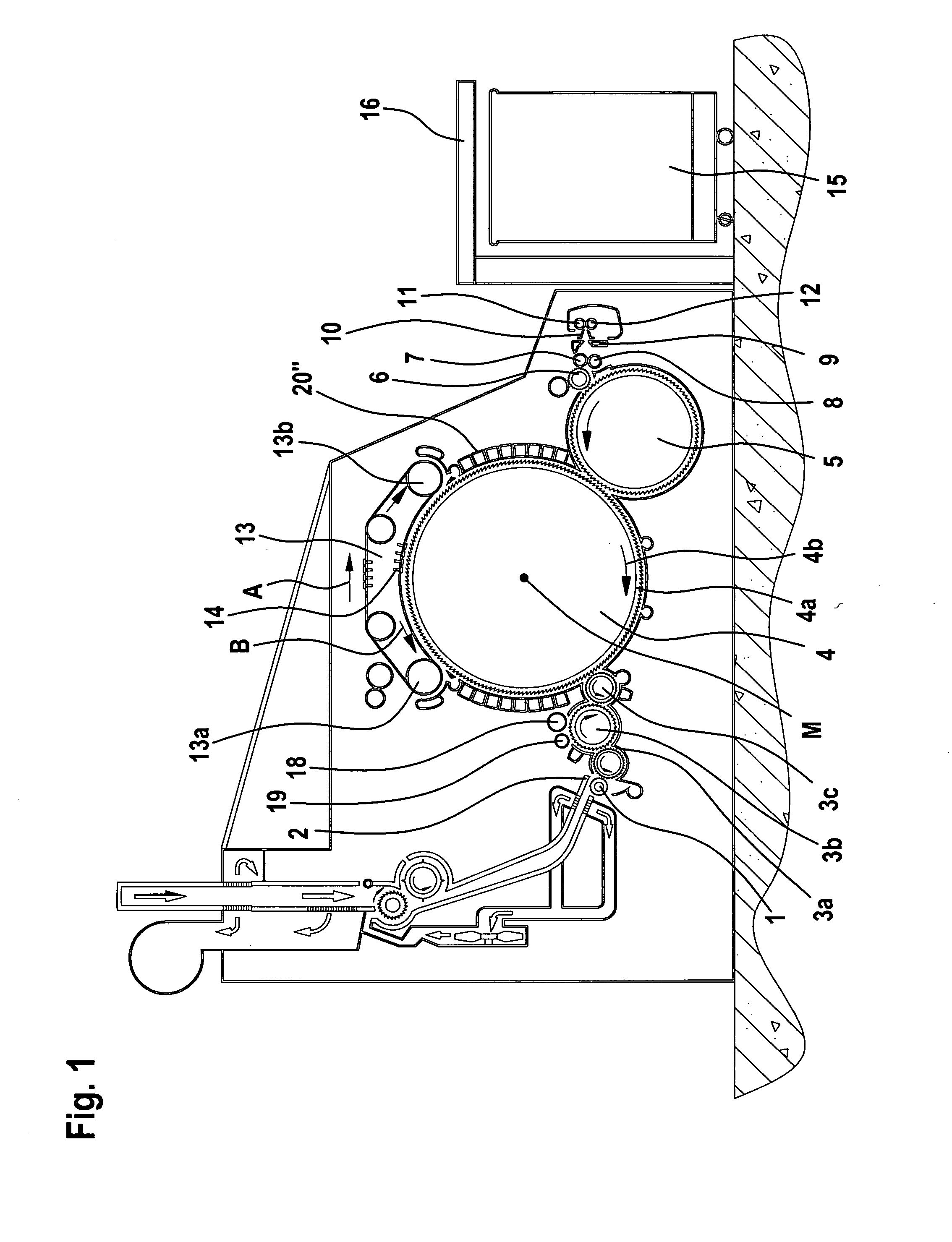
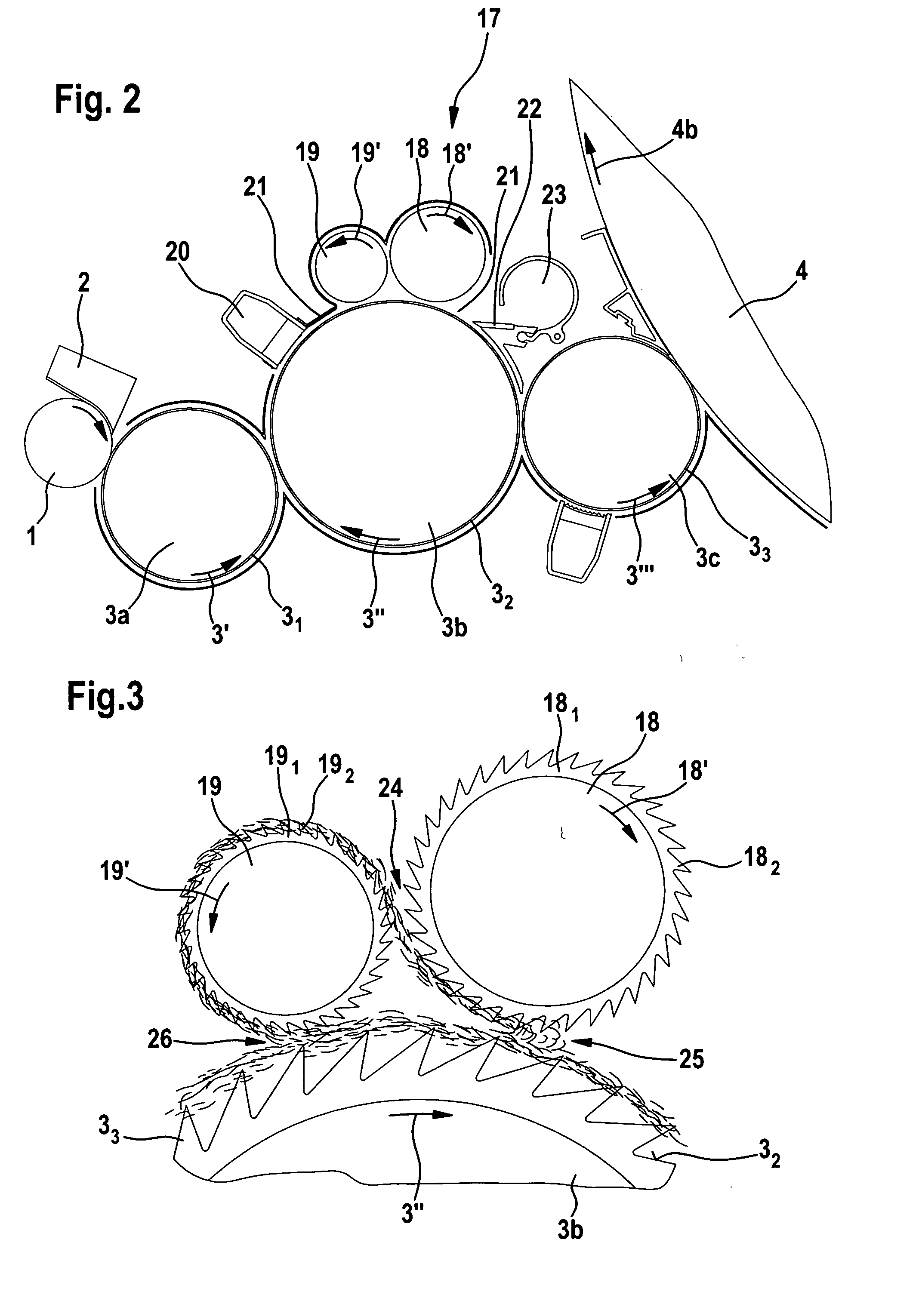
[0023]With reference to FIG. 1, a flat card, e.g. a TC 03 flat card made by Trutzschler GmbH & Co. KG of Mönchengladbach, Germany, has a feed roller 1, feed table 2, lickers-in 3a, 3b, 3c, cylinder 4, doffer 5, stripper roller 6, nip rollers 7, 8, web guide element 9, web funnel 10, delivery rollers 11, 12, revolving card top 13 with card top guide rollers 13a, 13b and flats 14, can 15 and can coiler 16. The directions of rotation of the rollers are indicated by curved arrows. Reference letter M denotes the centre point (axis) of the cylinder 4. Reference numeral 4a indicates the clothing and reference numeral 4b indicates the direction of rotation of the cylinder 4. Arrow A indicates the working direction. The curved arrows shown inside the rollers indicate the directions of rotation of the rollers. A first embodiment of the invention is provided at the licker-in 3b at which there is a cleaning device 17 comprising a first roller 18 (inverter) and a second roller 19 (stripper) whic...


PUM


Abstract

An apparatus on a textile machine for cleaning fibre material has a first roller for conveying a travelling fibre web, and second and third rollers which have respective nips with one another and with the first roller on rotation of the three rollers. The second roller is arranged downstream of the third roller and co-operates with the first roller so that fibre is detached, the fibre is transferred to the nip with the third roller and conveyed by the third roller to the nip with the first roller. The rollers have clothing with tips which are inclined in the direction of rotation. To improve the cleaning the front angle a of the tips of the second roller is about from 10° to 50° and the clothing gaps may be large to obtain a higher filling volume for fibres.

Description

CROSS REFERENCE TO RELATED APPLICATION[0001]This application claims priority from German Patent Application No. 10 2006 005 390.7 dated Feb. 3, 2006, the entire disclosure of which is incorporated herein by reference.BACKGROUND OF THE INVENTION[0002]The invention relates to an apparatus on a textile machine, for example a flat card, roller card or the like, for cleaning fibre material, for example of cotton.[0003]There is described in WO 01 / 92614 (also published as EP 1 290 252 B) a carding machine comprising a high-speed first or main roller, which is so adapted that it supports or conveys a travelling fibre web, associated second and third rollers, which have respective nips with one another and with the first roller on rotation of the three rollers, and drive means for rotation of the rollers, which drive means are so arranged that the second roller is rotated in a direction of rotation that is the same as that of the first roller and opposite to that of the third roller, wherein...

Claims


Application Information

Patent Timeline
IPC IPC(8): D01G15/00
CPCD01G15/18D01G15/84
Inventor SAEGER, NICOLEFRIEDRICH, ROLAND
Owner TRUETZSCHLER GMBH & CO KG
Why Eureka
Try Eureka