
Flocked cosmetic applicators

a cosmetic applicator and applicator technology, applied in the field of topical applicators, can solve the problems of not having the same soft feel as the foam tipped applicator, the applicator is not as durable as might be desired, and the foam is a relatively expensive element for use in the cosmetic applicator, so as to reduce the cross-sectional area, reduce the cost, and soften the consumer's fa

Inactive Publication Date: 2007-08-09
RISDON INT
View PDF4 Cites 66 Cited by
  • Summary
  • Abstract
  • Description
  • Claims
  • Application Information

AI Technical Summary

Benefits of technology

[0004]It is an object of the invention to provide a cosmetic applicator that can be fabricated from lower cost materials such as LDPE, HDPE, polyester, polypropylene or other plastics, and which will still provide a soft feel to the consumer's face.
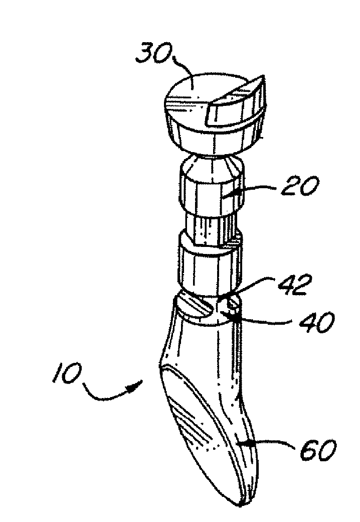
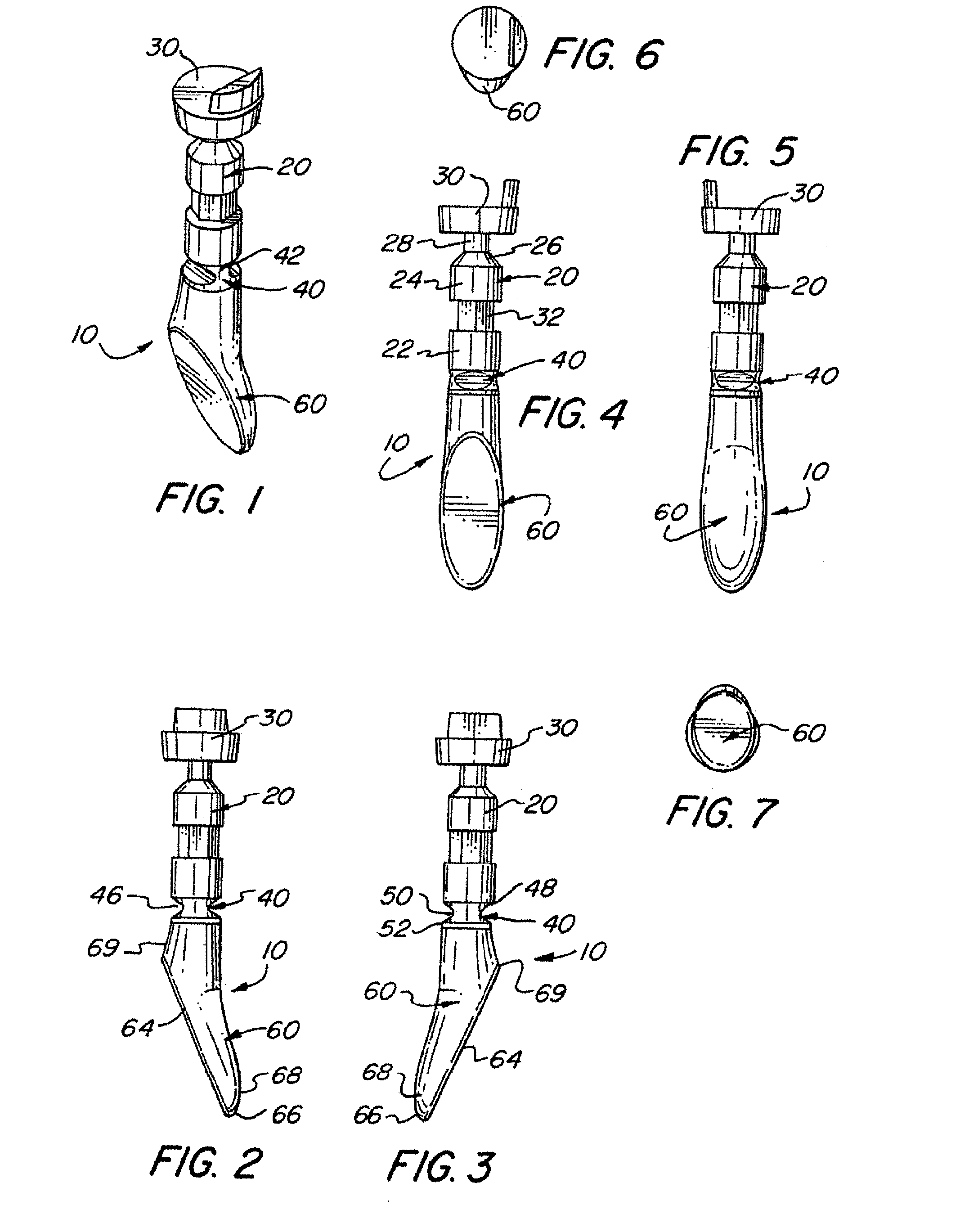
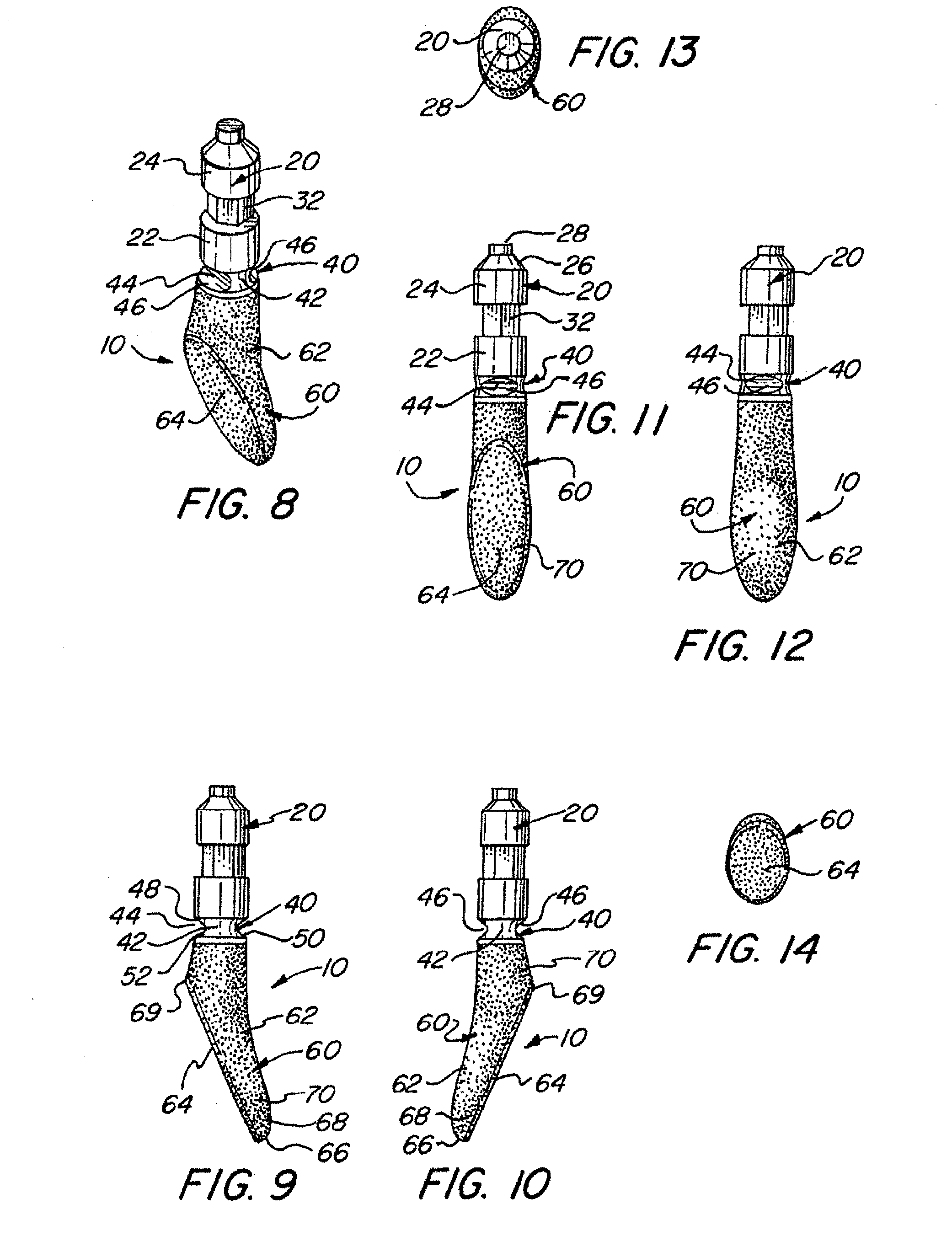
[0005]In accordance with the invention, a flocked cosmetic applicator has a mounting post connected to an applicator tip by a flexing element. The flexing element has a cutaway, reduced diameter portion, which may be provided by horizontal grooves formed on opposite sides of the flexing element, to provide flexibility by reducing its cross-sectional area. The applicator tip has a body and one or more flocked applicator surfaces. Preferred embodiments of the applicator tip include applicator surfaces which are angled relative to the body, and include a doefoot body, a flexible body, and a spatula body. A preferred applicator tip has a convex applicator surface. The design permits use of lower cost materials yet provides the sensation of softness to the user.

Problems solved by technology

However, such foam applicators are not as durable as might be desired, and foam, particularly latex foam, is a relatively expensive element for use in a cosmetic applicator.
Plastic applicators coated with flocking have been used, however, they do not have the same soft feel as foam tipped applicators.
In some designs they are perceived by the consumer user as having a hard, unpleasant feel.

Method used


Image

  • Flocked cosmetic applicators
  • Flocked cosmetic applicators
  • Flocked cosmetic applicators

Examples


first embodiment

[0060]Referring now to FIGS. 1-14, a cosmetic applicator 10 in accordance with the invention is shown. In FIGS. 1-7, cosmetic applicator 10 is shown as initially molded; in FIGS. 8-14, the same cosmetic applicator 10 is shown with the umbrella element 30 removed and flocking 70 applied. Cosmetic applicator 10, as shown in FIGS. 1-14, comprises an upper mounting element 20, a flexing element 40, and an applicator tip 60. Cosmetic applicator 10 is molded from LDPE, HDPE, polyester, polypropylene or other suitable plastic material, and in preferred embodiments is formed of HYTREL® polyester, HDPE or LDPE.

[0061]Upper mounting element 20 includes a lower endpiece 22 having a lower endpiece cross-sectional area, and an upper endpiece 24 having an upper endpiece cross-sectional area. Lower endpiece 22 and upper endpiece 24 are preferably generally cylindrical in shape. The upper endpiece 24 preferably has an upper conical section 26 tapering to a rod 28. Rod 28, as seen in FIGS. 1-7, is pr...

second embodiment

[0068]Referring now to FIGS. 15-28 a cosmetic applicator 210 in accordance with the invention is shown. In FIGS. 15-21, cosmetic applicator 210 is shown as initially molded; in FIGS. 22-28, the same cosmetic applicator 210 is shown with the umbrella element 230 removed and flocking 270 applied. Cosmetic applicator 210, as shown in FIGS. 15-28, comprises an upper mounting element 220, a flexing element 240, and an applicator tip 260.

[0069]Upper mounting element 220 includes a lower endpiece 222 having a lower endpiece cross-sectional area, and an upper endpiece 224 having an upper endpiece cross-sectional area. Lower endpiece 222 and upper endpiece 224 are preferably generally cylindrical in shape. The upper endpiece 224 preferably had an upper conical section 226 tapering to a rod 228. Rod 228, as seen in FIGS. 15-21, is provided with an umbrella element 230, which is removed after molding of the cosmetic applicator, leaving a shortened rod 228 as seen in FIGS. 22-28. A stem 232 con...

third embodiment

[0073]Referring now to FIGS. 29-40, a cosmetic applicator 310 in accordance with the invention is shown. In FIGS. 29-34, cosmetic applicator 310 is shown as initially molded; in FIGS. 35-40, the same cosmetic applicator 310 is shown with the umbrella element 330 removed and flocking 370 applied. Cosmetic applicator 310, as shown in FIGS. 29-40, comprises an upper mounting element 320, a flexing element 340, and an applicator tip 360.

[0074]As previously described in connection with the first and second embodiments of FIGS. 1-28, upper mounting element 320 includes a lower endpiece 322 connected by a stem 332 to an upper endpiece 324, which connects to a rod 328 and umbrella element 330.

[0075]A flexing element 340 connects the upper mounting element 320 to the applicator tip 260. The flexing element 340 has a portion 342 having a lesser cross-sectional area than the adjacent lower endpiece 322 of the upper mounting element 320 defined by the existence of at least one partially cutaway...


PUM


Abstract

Flocked cosmetic applicators have a mounting post connected to an applicator tip by a flexing element. The flexing element has a cutaway, reduced diameter portion, which may be provided by horizontal grooves formed on opposite sides of the flexing element, to provide flexibility by reducing its cross-sectional area. The applicator tip has a body and one or more flocked applicator surfaces. Preferred embodiments of the applicator tip include applicator surfaces which are angled relative to the body, and include a doefoot body, a flexible body, and a spatula body. A preferred applicator tip has a convex applicator surface. The design permits use of lower cost materials yet provides the sensation of softness to the user.

Description

CROSS-REFERENCE TO RELATED APPLICATIONS[0001]The present invention is a continuation-in-part of U.S. Design Patent Applications Nos. 29 / 245,935; 29 / 245,936; 29 / 245,937; and 29 / 245,938; all filed 30 Dec. 2005.FIELD OF THE INVENTION[0002]The present invention relates to the field of topical applicators for the skin, and particularly, cosmetic applicators suited for loading with a liquid cosmetic such as a colored lip cosmetic, a blush, an eyeshadow, or an eyeliner, and then applying the cosmetic to the skin.BACKGROUND OF THE INVENTION[0003]Cosmetic applicators are desirably designed to provide the consumer user with the perception that the applicator is soft in its feel on the skin. In foam applicators, e.g. such as applicators tipped with a latex foam or other foam, the sensation of softness is provided by the resilience of the foam. However, such foam applicators are not as durable as might be desired, and foam, particularly latex foam, is a relatively expensive element for use in a...

Claims


Application Information

Patent Timeline
IPC IPC(8): A45D40/26
CPCA45D40/262A45D34/04
Inventor MONTOLI, ANTONIO
Owner RISDON INT
Learn More