Stand system for adjusting viewing angle of monitor

a technology of viewing angle and monitor, which is applied in the field of stand system, can solve the problems of inconvenience for viewers, and achieve the effect of minimizing the torque required on the gear to move the base and minimizing the torque required on the gear

Inactive Publication Date: 2007-08-09
OH SUNG I +2
View PDF16 Cites 23 Cited by
  • Summary
  • Abstract
  • Description
  • Claims
  • Application Information

AI Technical Summary

Benefits of technology

[0007] The neck has a proximal end and a distal end. The proximal end is adapted to couple the base, and the distal end is adapted to couple to back side of a monitor. The distal end of the neck may be sized and configured so that with the monitor coupled to the distal end, the distance between the center of the monitor and the proximal end of the neck may be similar to the radius of curvature of the base. However, it is within the scope of the invention to have the distance between the center of the monitor and the proximal end of the neck to be greater or less than the radius of curvature of the base. With the stand system described above, the torque required on the gear to move the base may be minimized because the moment of inertia due to the mass of the monitor is minimized as the monitor tilts. As such, even a heavy TV such as a plasma TV can be tilted substantially along its center of gravity to minimize the torque required on the gear.

Problems solved by technology

Manually adjusting the viewing angle of the monitor, however, can be inconvenient for the viewer.

Method used


Image

  • Stand system for adjusting viewing angle of monitor
  • Stand system for adjusting viewing angle of monitor
  • Stand system for adjusting viewing angle of monitor

Examples


Embodiment Construction

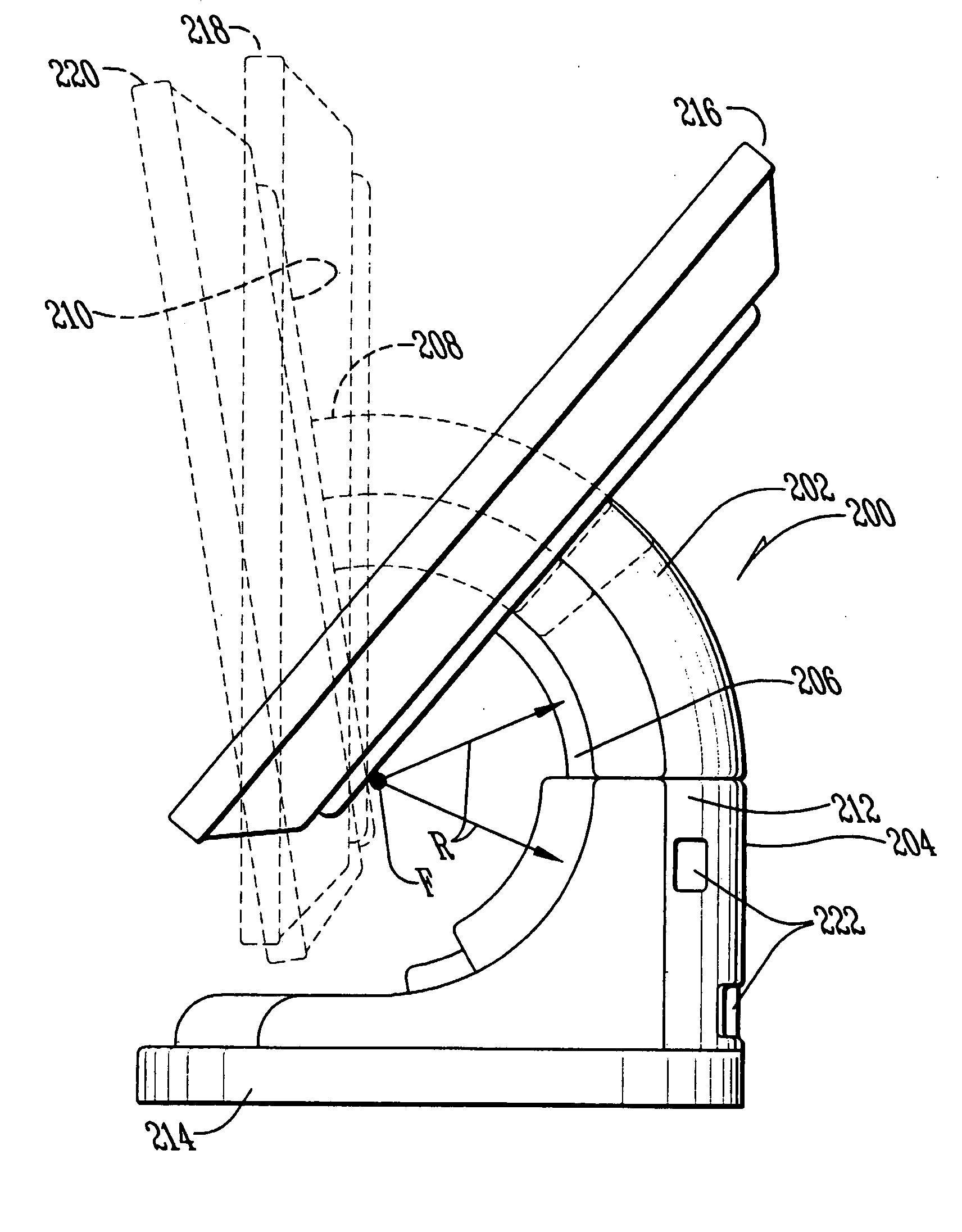
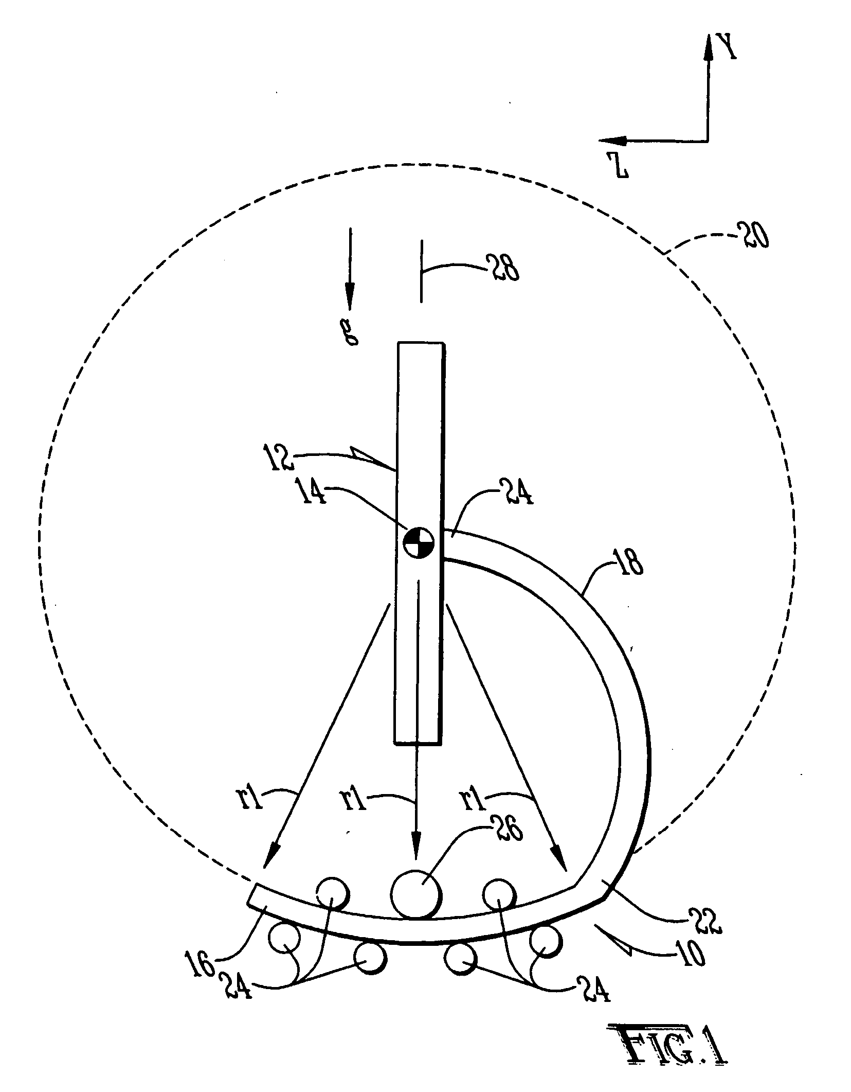
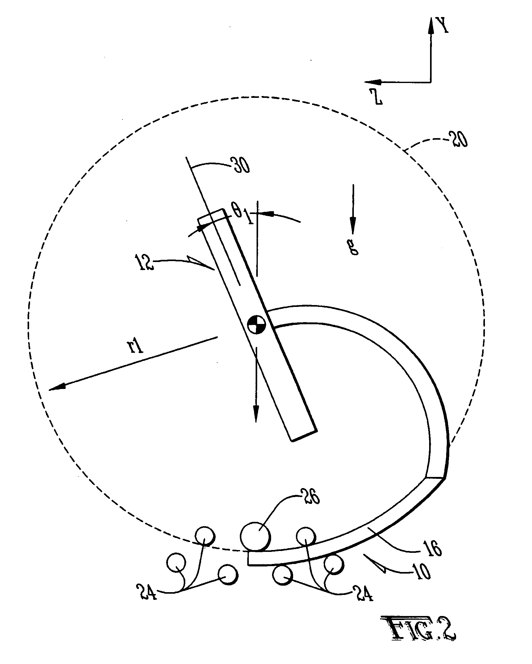
[0019]FIG. 1 shows a side view of a stand system 10, along the YZ plane, capable of tilting a monitor 12 substantially about its center axis 14. The stand system 10 includes a base 16 and a neck 18. The base 16 may have an arc configuration where the radius of curvature of the base has a radius r1. The radius r1 is the approximate distance between the center axis 14 and the base 16. Note that the partial circular hash lines are shown for illustrative purpose only to indicate that the base 16 may have an arc representing a portion of a circle 20 having a radius r1 where the center of the circle 20 is represented by the center axis 14.

[0020] The neck 18 may be provided between the monitor 12 and the base 16. The neck 18 may have a proximal end 22 and a distal end 24. The neck 18 may be sized so that the distance between the center axis 14 and the base 16 has a radius r1. Note that the neck may have a variety of configuration with the distance between the center axis 14 and the base 1...


PUM


Abstract

A stand system tilts a monitor up or down. The stand system can move the monitor manually or through one or more motors. The stand system has a base and a neck. The an arc configuration that slides on one or more rollers. The base may be engaged with a mechanism that slides the base along the rollers following the arc configuration of the base. The gear mechanism may be coupled to a motor to slide the base on the roller through a motorized action.

Description

RELATED APPLICATIONS [0001] This application claims priority to two provisional patent applications: (1) 60 / 758,636 filed Jan. 12, 2006; and (2) 60 / 831,640 filed Jul. 17, 2006, which are both incorporated by references.BACKGROUND OF THE INVENTION [0002] 1. Field of the Invention: [0003] This invention is directed to a stand system that is capable of adjusting the viewing angle of a monitor and, in particular, capable of adjusting the tilting angle of the monitor. [0004] 2. Background of the Invention: [0005] Flat panel monitors such as computer monitors, LCD TVs, plasma TVs, slim TVs, and the like (collectively referred to as “monitor(s)”) are becoming popular because of their slim appearance. Generally, the monitors are mounted onto a wall or either placed on the floor or placed on top of a table stand. Once a monitor is in position, a viewer generally adjusts the viewing angle of the monitor manually to a new viewing position so that the viewer may more comfortably view the monito...

Claims


Application Information

Patent Timeline
Patent Type & Authority Applications(United States)
IPC IPC(8): F16M11/02
CPCF16M11/10F16M2200/08F16M11/18
Inventor OH, SUNG I.JUN, SEUNG GWONKANG, BYUNG-KIL
Owner OH SUNG I
Why Eureka
Try Eureka