Conical washer spring support

a technology of washer springs and supports, applied in the direction of machine supports, wound springs, other domestic objects, etc., can solve the problems of difficult installation, limited placement options of spring supports, and many times less than 14′′ of thermal and dynamic displacement in pde, and achieve good shock absorption and energy dissipation

Inactive Publication Date: 2007-08-09
DISC SPRING TECH
View PDF1 Cites 13 Cited by
  • Summary
  • Abstract
  • Description
  • Claims
  • Application Information

AI Technical Summary

Benefits of technology

[0034]4) The support is largely self-dampening, particularly stacking the conical washer in “series”, giving good shock absorption and ene...

Problems solved by technology

However, thermal and dynamic displacements in PDE are many times less than ¼″.
The obstructions that occur often limit th...

Method used


Image

  • Conical washer spring support
  • Conical washer spring support
  • Conical washer spring support

Examples


Embodiment Construction

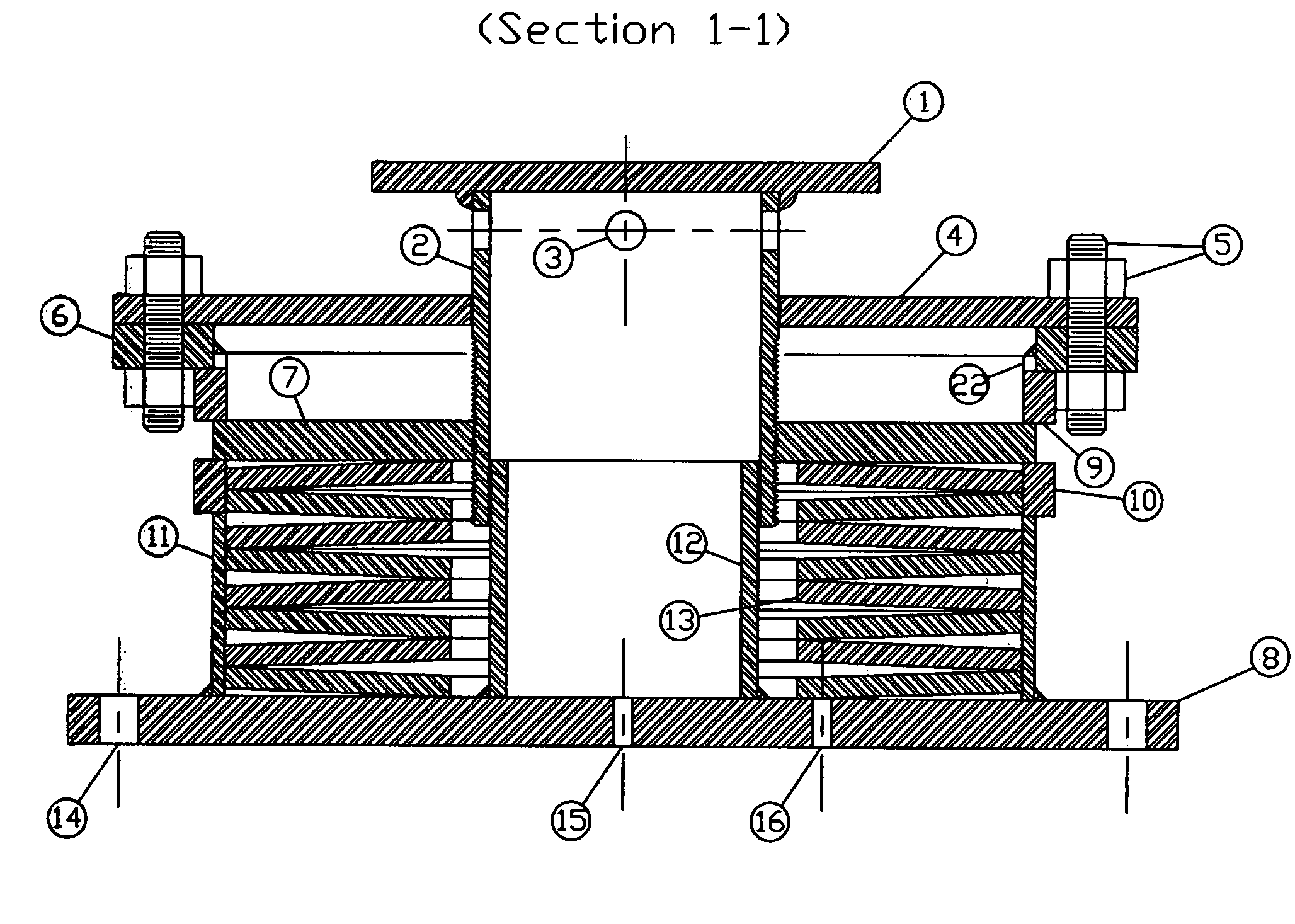
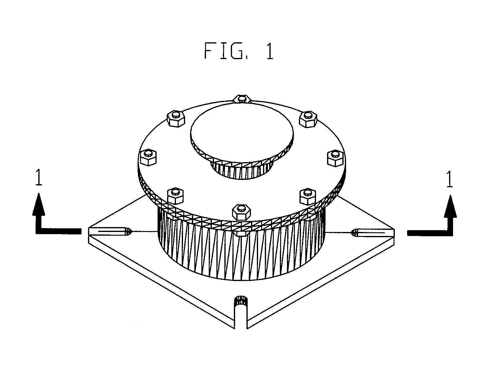
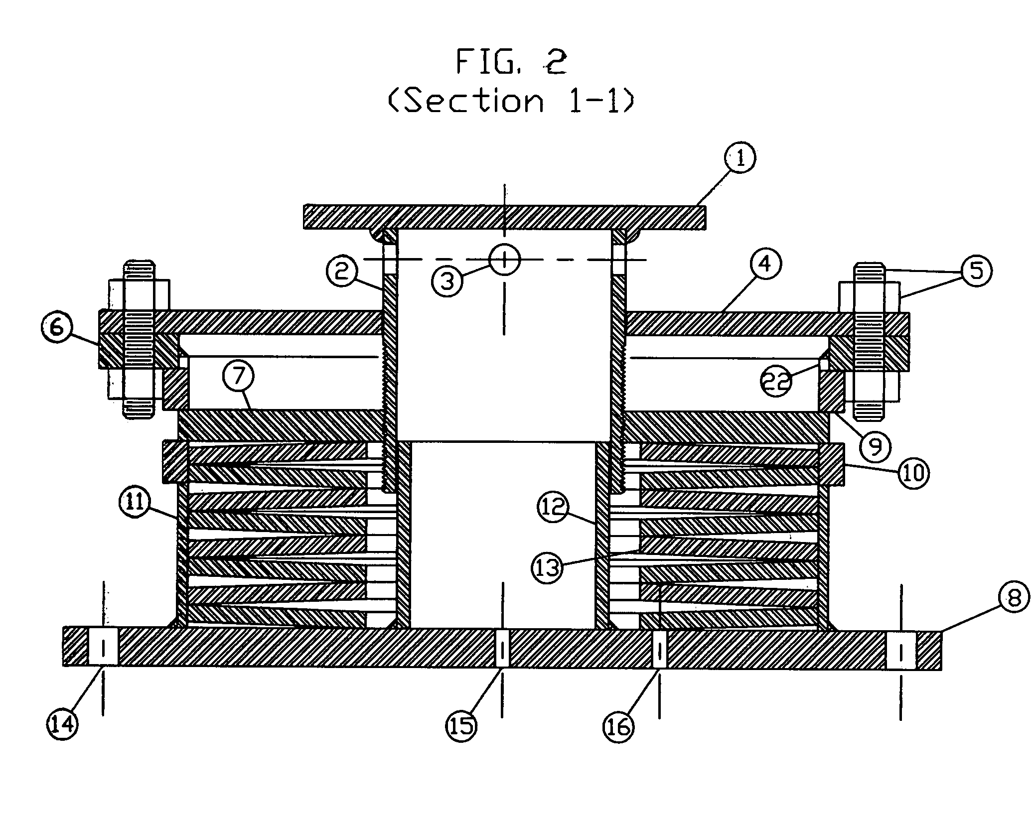
[0051]Referencing FIGS. 1-3, each drawing is an example of a typical support type of a Conical Washer Spring Support. The load flange 1 is a flat disk with a concentric, circular lip welded to the disk's bottom surface about the disk's centerline. The load flange is fit transversely onto the load column 2. The load column 2, assembled vertically, is a piston shaped cylinder machined flat on its top edge (mating with the load flange 1) and threaded at its lower end. When assembled, the threaded end of the load column 2 engages the load plunger 7, which in turn, is in contact with the top edge of the conical washer (s) 13. The load plunger 7 is a donut shaped flat plate with one lug extending radially from its center on either side of its outer edge. From the plunger's centerline, these two tabs extend out, symmetrically. The load column's inner surface is guided by the smaller, cylindrical guide 12, which is centered on the base 8. At the upper end of the load column, four equally sp...


PUM


Abstract

This invention relates to a support or hanger utilizing a conical washer spring or set of conical washer springs displaying variable load characteristics. When installed, both types (support or hanger) allow for small movements in pipe, ductwork or equipment (PDE), thus, allowing for the thermal growth of PDE. Conventionally, helical coil spring supports are chosen to meet the load capacities of PDE but are reluctantly used because of their large size. By using conical washer springs, the size of the support is substantially reduced making it a more useable device. A smaller, more compact design proves to increase the support/hanger's application making it more stable to place under piping and even under reciprocating motion equipment like generators and pumps. For small displacements, it is found that this invention behaves in the same manor as a conventional helical coil spring support under the same applied loads.

Description

CROSS-REFERENCE TO RELATED APPLICATIONS[0001]This application claims priority under 35 U.S.C. §119(e) to U.S. Provisional Patent Application Ser. No. 60 / 765,348 entitled Conical Washer Spring Support, filed Feb. 6, 2006. The complete disclosure of that application is herein incorporated by reference for all purposes.U.S. Patent DocumentsU.S. Pat. No.Issued DateInventorClassification5009386June., 1989Berger248 / 6134627593December, 1986A. J. Salter248 / 5615944288August, 1999Whitney / Birch248 / 0584238102December, 1980C. J. Salter248 / 5434640487February, 1987A. J. Salter248 / 5714206898June, 1980C. J. Salter248 / 5613833194September, 1974A. J. Salter248 / 0546517060February, 2003Z. A. Kemeny267 / 1365564664October, 1996M. Oschwald  248 / 288.515482406January, 1996E. J. Arlt, III  405 / 195.15458313October, 1995R. Tie et al.248 / 6134200256April, 1980P. H. Thiel248 / 5483873079March, 1975F. Kuus267 / 1623856242December, 1974B. D. Cook248 / 0203770232November, 1973J. C. Blake248 / 0213107905October, 1963C. D. Lucas...

Claims


Application Information

Patent Timeline
IPC IPC(8): F16F1/12
CPCF16F3/02F16F1/32
Inventor LEONARDI, KIRK V.MAKADIA, BHARAT VALLABHDASREMANN, KLAUS PETERTAYLOR, JAMES OCTAVIUS
Owner DISC SPRING TECH
Why Eureka
Try Eureka