

Total reflection fluorescent microscope
a fluorescent microscope and fluorescent microscope technology, applied in the field can solve the problems of large occupying space, high cost of laser light beam producing laser beam, and high cost of total reflection fluorescent microscop
- Summary
- Abstract
- Description
- Claims
- Application Information
AI Technical Summary
Benefits of technology
Problems solved by technology
Method used
Image

Examples
first embodiment
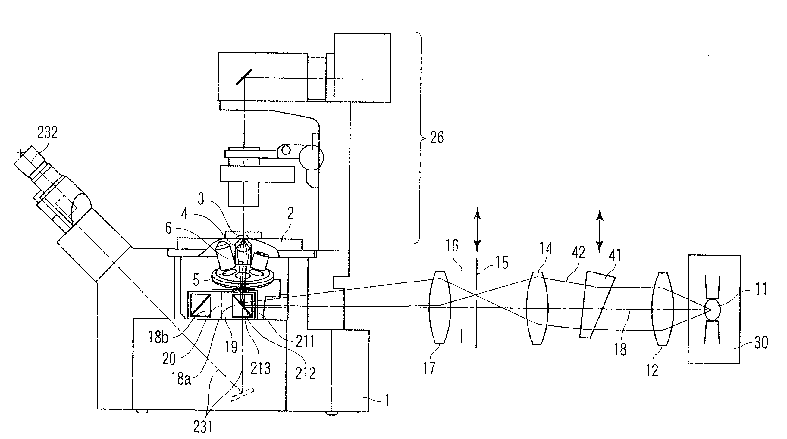
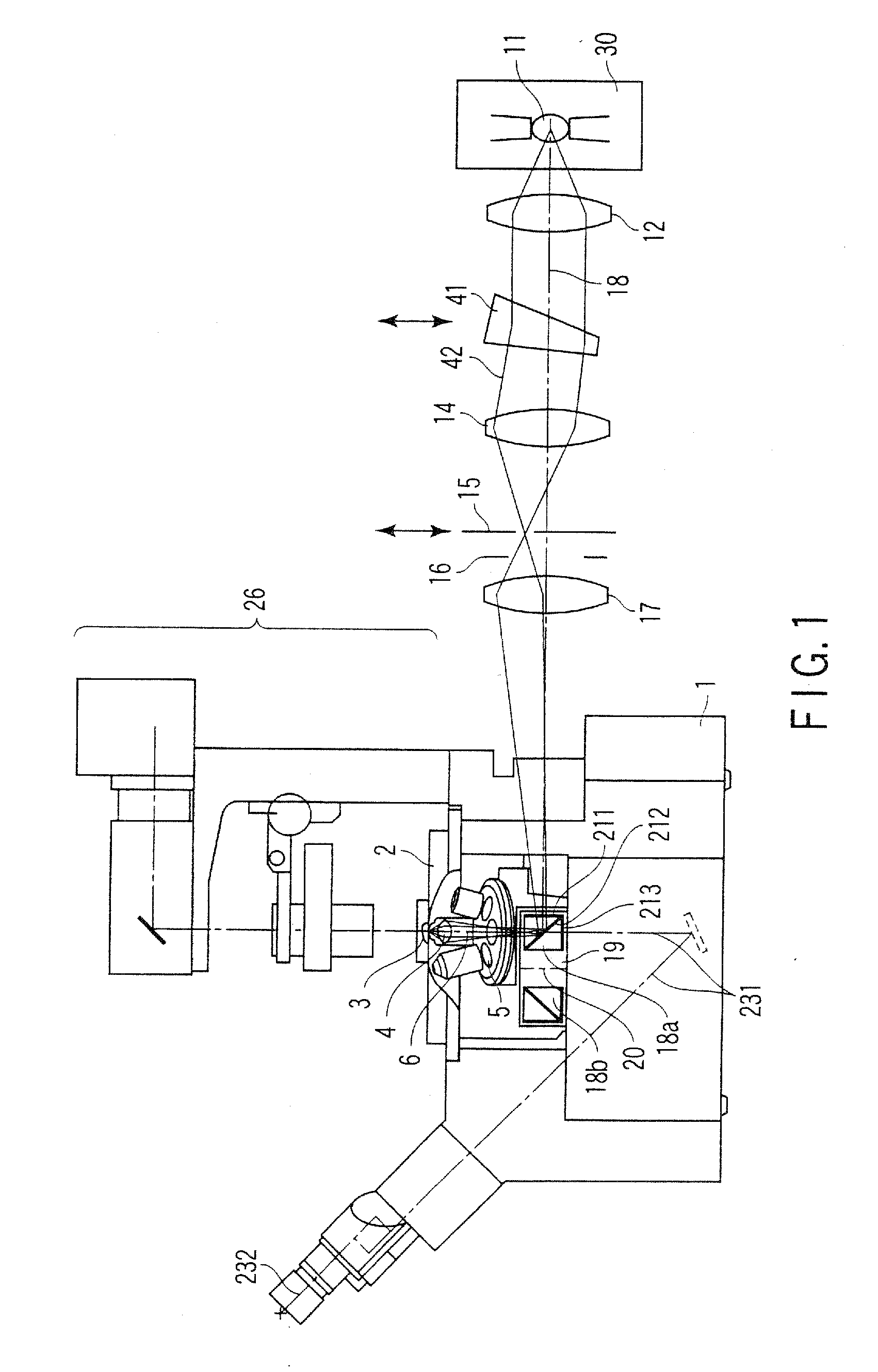
[0040]FIG. 1 is a diagram showing a schematic configuration of a total reflection fluorescent microscope to which the present invention is applied. In this case, FIG. 1 shows an example of an inverted microscope for performing observation by an objective lens disposed below a specimen.
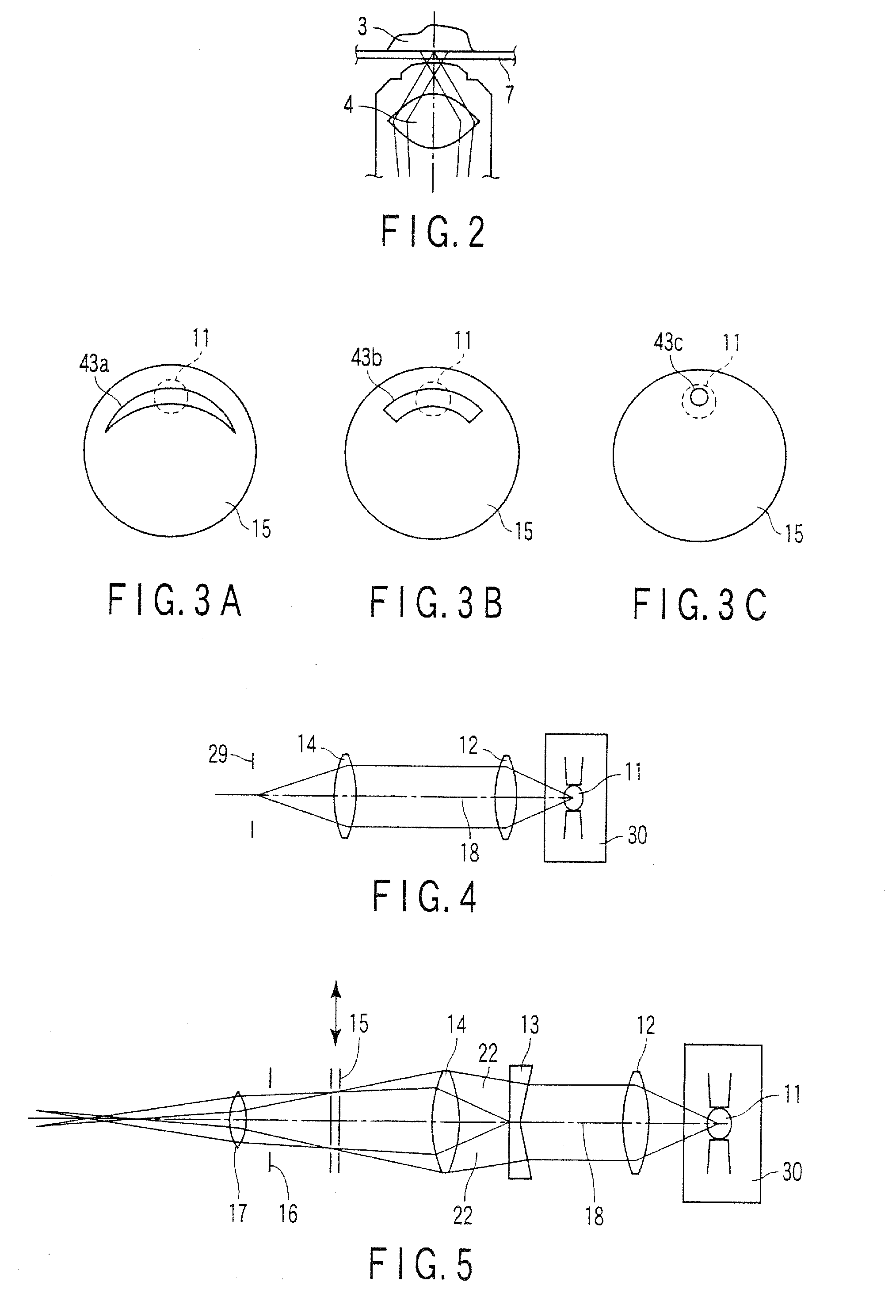
[0041] In FIG. 1, a stage 2 is disposed in an upper part of a microscope main body 1. A specimen 3 is laid on the stage 2. In this case, as shown in FIG. 2, a cover glass 7 is disposed under the specimen 3. An objective lens 4 is disposed under the cover glass 7 via oil (not shown).
[0042] A revolver 5 is disposed under the specimen 3. The revolver 5 is held in the microscope main body 1. The revolver 5 holds a plurality of objective lenses 4. When the revolver 5 rotates, it is possible to selectively dispose the objective lens 4 having a magnification or a type required for the observation on an observation optical axis 6. When the revolver 5 vertically moves along the observation optical axis 6 by a...
second embodiment
MODIFICATION OF SECOND EMBODIMENT
[0103] Next, a modification of the second embodiment will be described.
[0104] The modification of the second embodiment is an example in which the illumination efficiency is raised without using the wedge prism, and will be described with reference to FIGS. 10A and 10B.
[0105] As shown in FIG. 10A, the light source 11 is movable vertically in an arrow direction along the plane crossing the illuminative light axis 18 at right angles. Moreover, the light source 11 can be positioned in two positions including a position on the illuminative light axis 18 and a lower position deviating slightly from the illuminative light axis 18.
[0106] To perform the total reflection fluorescent observation, the light source 11 is set in a position denoted with reference numeral 11′ slightly deviating from the illuminative light axis 18. Then, as shown in FIG. 10B, the light beams from the light source 11′ are formed into the parallel light beam having a predetermined ...
third embodiment
MODIFICATION OF THIRD EMBODIMENT
[0117] Next, a modification of the third embodiment will be described
[0118] The modification of the third embodiment is an example including another means for reducing the illumination unevenness, and will be described with reference to FIGS. 14A and 14B.
[0119] In this case, the wedge prism 13 is disposed in the optical path between the collector lens 12 and the condenser 14 in the same manner as in the second embodiment. Moreover, a slit in which the annular opening 25 is formed along the peripheral edge portion as shown in FIG. 14B is used as the slit 15. Further-more, in this state, the wedge prism 13 is rotated at a high speed in a direction of an arrow 33 using the illuminative light axis 18 which is a rotational center. In this case, the prism is rotated once at about 30 msec in the visual observation, or rotated at a rotation number higher than a scanning speed of photo-detection, when photo-detection means such as CCD. Accordingly, as shown ...
PUM
 Abstract
Description
Claims
Application Information