Mains wire antenna for wireless interface applications

Inactive Publication Date: 2007-08-09
KONINKLIJKE PHILIPS ELECTRONICS NV
View PDF7 Cites 18 Cited by
  • Summary
  • Abstract
  • Description
  • Claims
  • Application Information

AI Technical Summary

Benefits of technology

[0005] The present invention seeks to provide an improved wireless control interface for a lamp driver. Prefera

Problems solved by technology

For a lamp driver the situation is, however, complicated by the fact that the application has a metal housing.
The housing will isola

Method used


Image

  • Mains wire antenna for wireless interface applications
  • Mains wire antenna for wireless interface applications

Examples


first embodiment

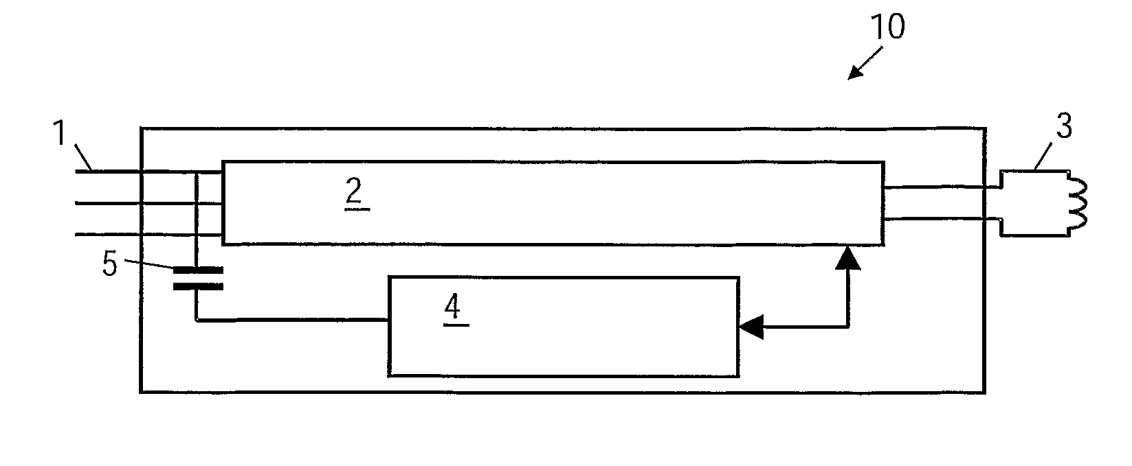
[0027] a device 10 according to the present invention is illustrated in FIG. 1. The lamp is in the illustrated embodiment a fluorescent lamp. The figure illustrates the main components present in a lamp driver. The lamp driver is connected to mains 1 for example by direct cable connection to live (L), neutral (N) and possible protective earth (PE) of a mains network. The lamp driver comprises a driver circuit 2 connected to the electrodes 3 of the lamp (only one electrode shown here). The driver circuit is capable of controlling light emission, thus capable of at least starting the emission process of a fluorescent lamp and maintaining a substantially constant light emission level from the lamp. The lamp driver circuitry is communicatively connected to a control interface 4. The control interface 4 being able to extract or impose an alternating signal from or to the at least one of the mains wires 1 by use of a capacitive coupling 5.

[0028] The control interface 4 receives or transmi...

embodiment 20

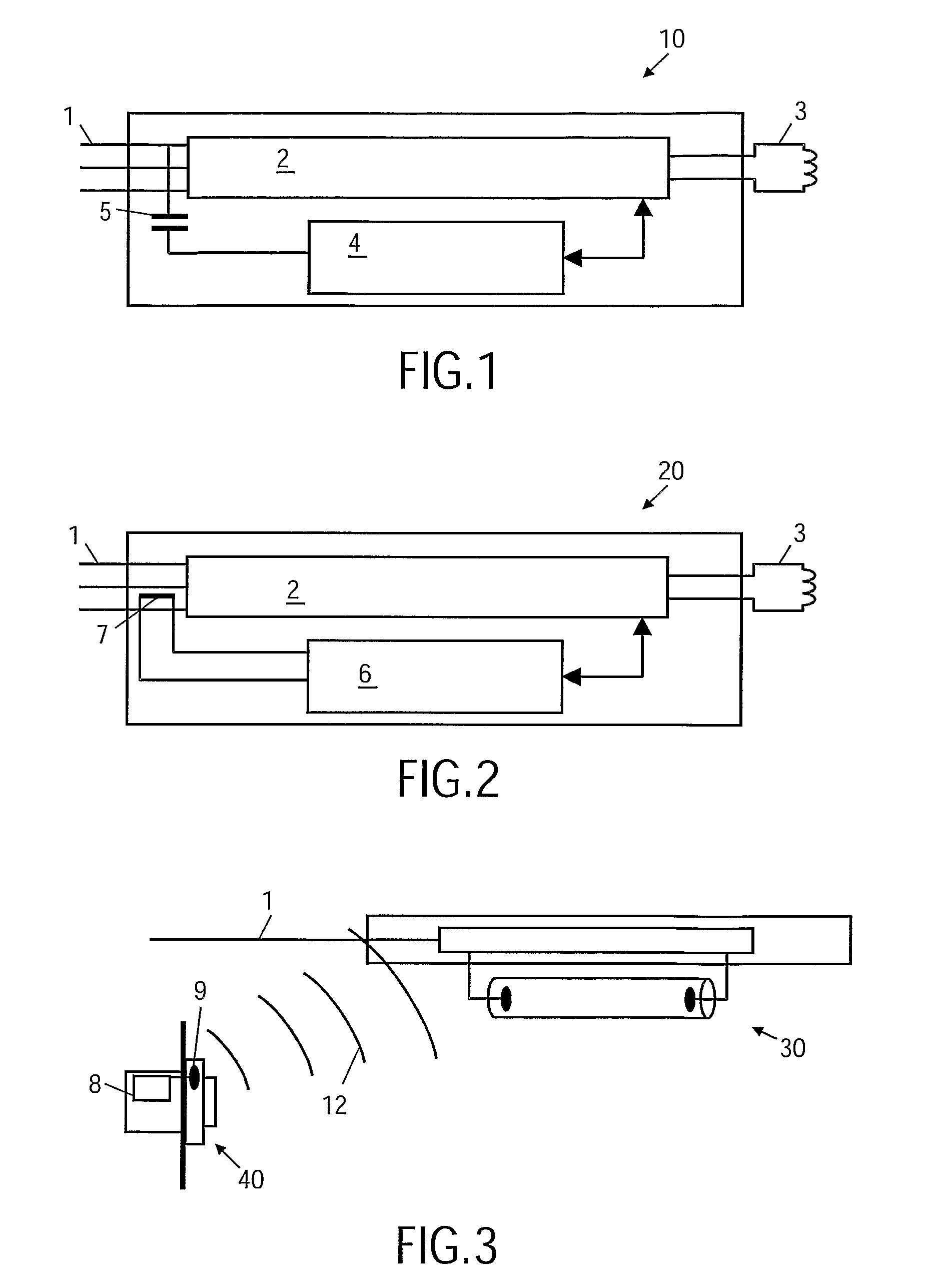
[0029] In FIG. 2 a different embodiment 20 is illustrated. In this embodiment the control interface 6 is able to extract or impose an alternating signal from or to least one of the mains wires 1 by means of an inductive coupling 7. As an example of an inductive coupling a Lecher line transformer may be used. In the figure, the transformer establishes an RF coupling to the neutral of the mains.

[0030] Wireless communication between a wall unit 40 and a fluorescent lamp 30 is illustrated in FIG. 3. The wall unit acts as an interface for a user to communicate control signals to the lamp, such as turning the lamp on or off, dim the ballast of a fluorescent lamp, etc. The wall unit comprises a wireless communication circuit 8 including an antenna 9. The antenna may be completely comprised within the wall unit by fabricating the wall unit in a suitable material, such as a material which is transparent to electromagnetic radiation, e.g. plastic.

[0031] The wall unit may transmit an electrom...


PUM


Abstract

The present invention deals with wireless control of a lamp such as a fluorescent lamp controlled by a ballast with a wireless control interface for RF communication. The receiver input and the transmitter output of the control interface module are connected to one or more mains wires by means of (a) coupling capacitor(s) or a Lecher line transformer. During operation the one or more mains wires serve as the lamp antenna.

Description

FIELD OF THE INVENTION [0001] The invention relates to wireless control of a lamp and in particular relates to the architecture of the antenna of the lamp's control interface. BACKGROUND OF THE INVENTION [0002] Lighting control in an office or commercial building has gone through several stages ranging from “on / off”-control of a single lamp or a group of lamps, through dimming of a single lamp or a group of lamps, to advanced control of the lighting in an entire building. In normal lighting systems it is the individual lamp drivers of the luminaires that are controlled. The traditional lamp driver systems are wired control interface systems, such as the standard 1-10 V dimming interface and more recently digital systems, such as the Digital Addressable Lighting Interface (DALI). The interface systems are moving towards wireless interfaces, such as systems implementing the ZigBee standard, a system that uses radio frequencies around 2.4 GHz. [0003] A wireless interface using electrom...

Claims


Application Information

Patent Timeline
IPC IPC(8): F21V33/00H04B3/54H05B37/02
CPCH04B3/54H05B37/0272H04B2203/5458H05B47/195
Inventor BUIJ, ARNOLD WILLEMBEIJ, MARCELWESSELS, JOHANNES HENDRIK
Owner KONINKLIJKE PHILIPS ELECTRONICS NV
Why Eureka
Try Eureka