Antenna through the use of lamp electrodes

a technology of lamp electrodes and antennas, applied in the direction of electric controllers, instruments, ignition automatic control, etc., can solve the problems of blocking the transmission and reception of electromagnetic signals, complicated situation, etc., and achieve the effect of improving the wireless control interface, alleviating or reducing one or two

Inactive Publication Date: 2010-05-11
THE YOKOHAMA RUBBER CO LTD +1
View PDF14 Cites 14 Cited by
  • Summary
  • Abstract
  • Description
  • Claims
  • Application Information

AI Technical Summary

Benefits of technology

[0005]The present invention seeks to provide an improved wireless control interface for a lamp driver. Preferably, the invention alleviates or mitigates one or more of the above disadvantages singly or in any combination.
[0009]In a wirelessly controlled lamp two features are necessarily fulfilled. The lamp is capable of emitting light to the surroundings and the control interface is capable of receiving control signals though connection to an antenna. In the present invention, these two features may be combined since the at least first electrode may be used in connection with generating and maintaining the emission of light, and may also be used as the antenna of the lamp. This is an advantage since a separate antenna may be avoided and thereby facilitating a simplified design of the control system of the lamp, leading to reducing cost of the system, smaller systems, etc. As an important consequence no restriction from the presence of an antenna is imposed on the design of the lamp driver housing, the material of the lamp driver housing, or on the surroundings of the lamp driver.

Problems solved by technology

For a lamp driver the situation is, however, complicated by the fact that the application has a metal housing.
The housing will isolate an internal antenna from the environment, thereby largely blocking the transmission and reception of the electromagnetic signals.

Method used


Image

  • Antenna through the use of lamp electrodes
  • Antenna through the use of lamp electrodes

Examples


first embodiment

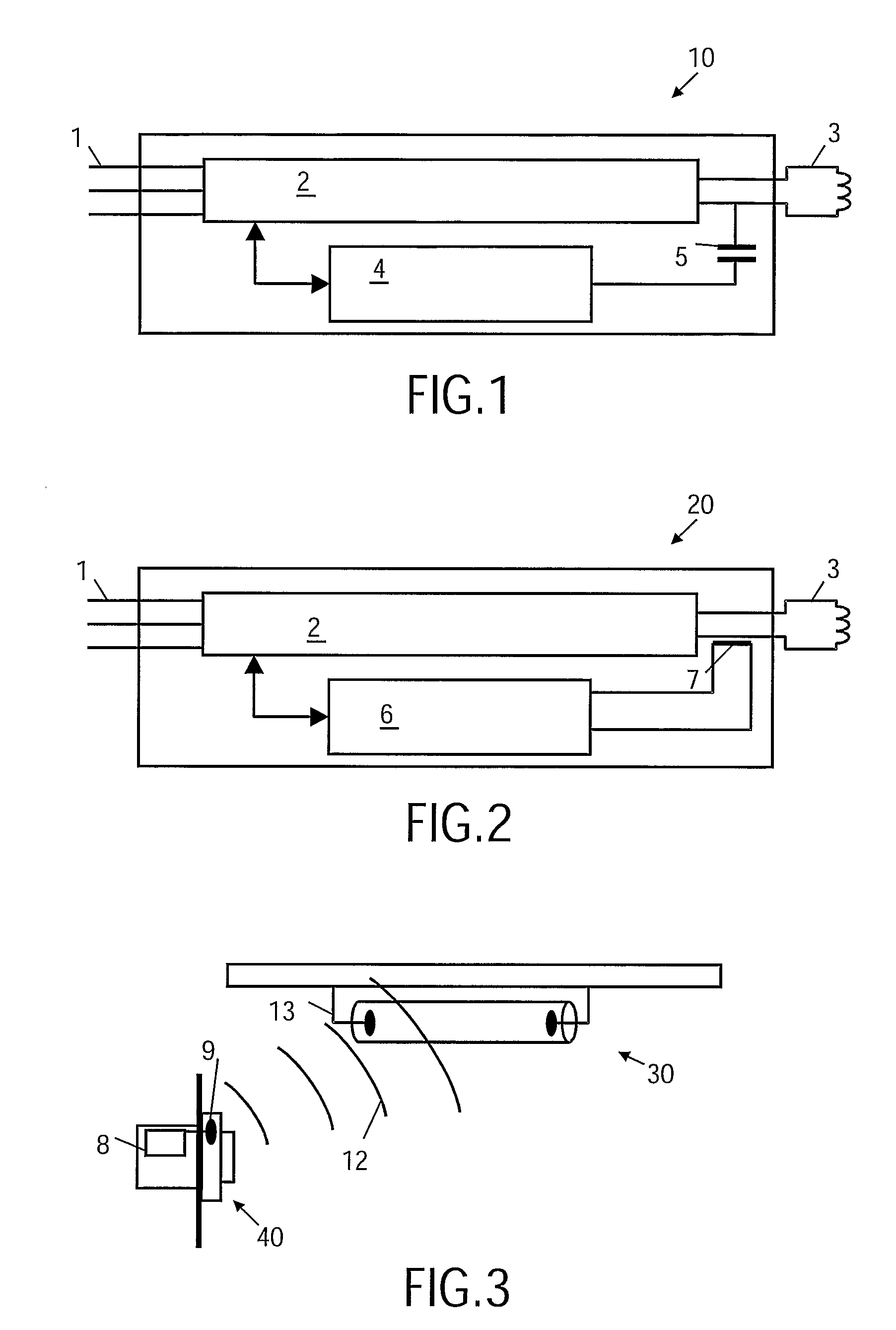
[0026]a device 10 according to the present invention is illustrated in FIG. 1. The lamp is in the illustrated embodiment a fluorescent lamp. The figure illustrates the main components present in a lamp driver. The lamp driver is connected to mains 1 for example by direct cable connection to live (L), neutral (N) and possible protective earth (PE) of a mains network. The lamp driver comprises a driver circuit 2 capable of controlling light emission, thus capable of at least starting the emission process of a fluorescent lamp and maintaining a substantially constant light emission level from the lamp. The lamp driver circuitry is communicatively connected to a control interface 4. The control interface 4 being able to extract or impose an alternating signal from or to the at least first electrode 3 by use of a capacitive coupling 5.

[0027]The control interface 4 receives or transmits data to or from an external unit through the at least first electrode 3 being the antenna. In the recei...

embodiment 20

[0028]In FIG. 2 a different embodiment 20 is illustrated. In this embodiment the control interface 6 is able to extract or impose an alternating signal from or to the least first electrode 3 by means of an inductive coupling 7. As an example of an inductive coupling a Lecher line transformer may be used.

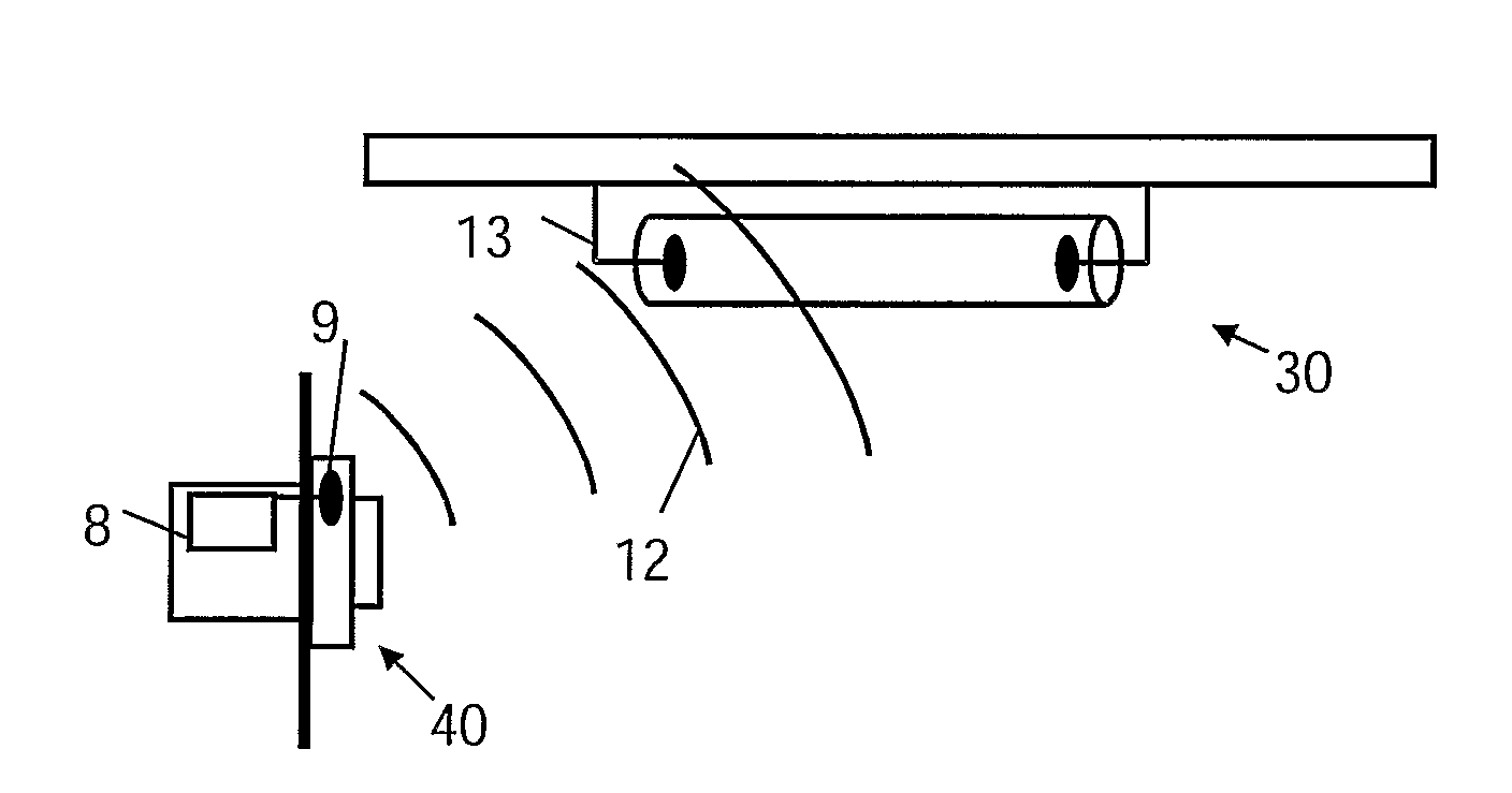
[0029]Wireless communication between a wall unit 40 and a fluorescent lamp 30 is illustrated in FIG. 3. The wall unit acts as an interface for a user to communicate control signals to the lamp, such as turning the lamp on or off, dim the ballast of a fluorescent lamp, etc. The wall unit comprises a wireless communication circuit 8 including an antenna 9. The antenna may be completely comprised within the wall unit by fabricating the wall unit in a suitable material, such as a material which is transparent to electromagnetic radiation, e.g. plastic.

[0030]The wall unit may transmit an electromagnetic signal 12 that can be received by the lamp by use of one of the electrodes 13 as an an...


PUM


Abstract

A wireless control is provided for a lamp, such as a fluorescent lamp, controlled by a ballast with a wireless control interface for RF communication. The receiver input and the transmitter output of the control interface module are connected to one or more electrode wires by a coupling capacitor(s) or a Lecher line transformer. During operation the lamp electrodes serve as the lamp antenna.

Description

FIELD OF THE INVENTION[0001]The invention relates to wireless control of a lamp and in particular relates to the architecture of the antenna of the lamp's control interface.BACKGROUND OF THE INVENTION[0002]Lighting control in an office or commercial building has gone through several stages ranging from “on / off”-control of a single lamp or a group of lamps, through dimming of a single lamp or a group of lamps, to advanced control of the lighting in an entire building. In normal lighting systems it is the individual lamp drivers of the luminaires that are controlled. The traditional lamp driver systems are wired control interface systems, such as the standard 1-10 V dimming interface and more recently digital systems, such as the Digital Addressable Lighting Interface (DALI). The interface systems are moving towards wireless interfaces, such as systems implementing the ZigBee standard, a system that uses radio frequencies around 2.4 GHz.[0003]A wireless interface using electromagnetic...

Claims


Application Information

Patent Timeline
Patent Type & Authority Patents(United States)
IPC IPC(8): G05B11/01H05B37/02
CPCH05B37/0272H05B47/19H05B47/195
Inventor WESSELS, JOHANNES HENDRIK
Owner THE YOKOHAMA RUBBER CO LTD
Why Eureka
Try Eureka