Optical disk apparatus and recording parameters setting method

a technology of optical disk and setting method, which is applied in the field of optical disk apparatus and recording data, can solve the problems of not being different from other conventional technologies, spending time unnecessarily, and consuming corresponding zones very fast, and achieves the effect of evaluating the quality of test signals very efficiently

Inactive Publication Date: 2007-08-09
HITACHI LTD +1
View PDF4 Cites 24 Cited by
  • Summary
  • Abstract
  • Description
  • Claims
  • Application Information

AI Technical Summary

Benefits of technology

[0008]It is, therefore, an object of the present invention is to reduce the time required for setting an optimum recording parameter, by carrying out a recording parameter learning more efficiently.

Problems solved by technology

However, it is not different from other conventional technologies because a specific test signal in a specific test writing area is still used for test writing.
For instance, in the case of a DVD-RAM disk, because a region exclusive for test writing is provided around an inner peripheral side and an outer peripheral side of the data recording region of the disk, a pickup needs to move towards a corresponding region during test writing, spending time unnecessarily.
Resultantly, a corresponding zone is consumed very fast and an optimum recording parameter may not be derived accurately.

Method used


Image

  • Optical disk apparatus and recording parameters setting method
  • Optical disk apparatus and recording parameters setting method
  • Optical disk apparatus and recording parameters setting method

Examples


Embodiment Construction

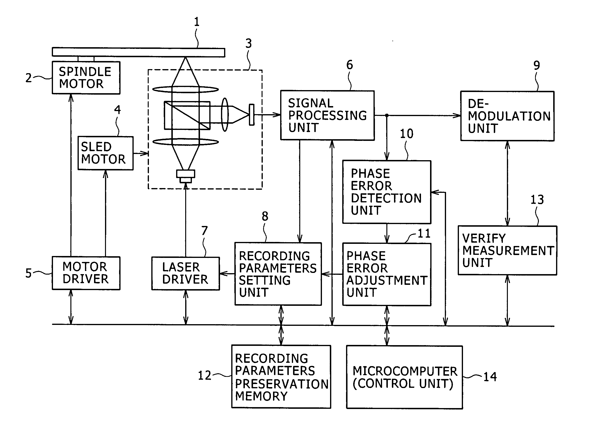
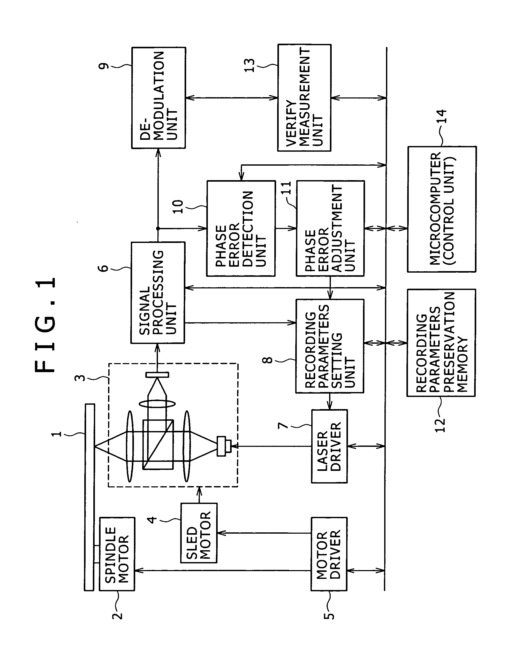
[0020]FIG. 1 is a block diagram showing an optical disk apparatus according to one embodiment of the present invention. The apparatus of this embodiment rotates an optical disk 1 with a spindle motor 2. A pickup3 irradiates a laser beam emitted from a semiconductor laser onto a recording surface of the optical disk 1, records / reproduces data or a test writing test signal and detects a reflected light from the optical disk 1. At this time, a data recording region of the optical disk 1 is used for recording / reproducing the data, and a test writing region is used for recording / reproducing the test signal. The pickup 3 includes a built-in objective lens and an actuator for adjusting the position of the objective lens, taking part in adjustment of focus and tracking. A sled motor 4 moves the pickup 3 in a radial direction on the optical disk. A motor driver 5 provides a drive signal for driving the spindle motor 2, the sled motor 4 or the actuator.

[0021]A signal processing unit 6 generat...


PUM

PropertyMeasurementUnit
phase erroraaaaaaaaaa
lengthaaaaaaaaaa
poweraaaaaaaaaa

Abstract

An optical disk apparatus and a recording parameters setting method are provided to more effectively execute recording parameter learning during data recording on the optical disk, thereby shortening the time required for setting an optimum recording parameter. A phase error detection unit detects a phase error amount from a reproduction signal of actual data being recorded. A phase error adjustment unit adjusts recording parameters (recording strategy) set by a recording parameters setting unit based on the detected phase error amount. The phase error amount detection is executed simultaneously with a verify process of the actual data. If a verify process judgment results says that a target quality is not attained, test writing by a test signal is not executed but the adjustment of recording parameters is conducted on the basis of the phase error amount.

Description

CLAIM OF PRIORITY[0001]The present application claims priority from Japanese application serial no. JP 2006-031053, filed on Feb. 8, 2006 the content of which is hereby incorporated by reference into this application.BACKGROUND OF THE INVENTION[0002](1) Field of the Invention[0003]The present invention relates to an optical disk apparatus recording data on an optical disk and recording parameters setting method, more specifically, to a technology for executing an efficient setting process of recording parameters.[0004](2) Description of the Related Art[0005]An optical disk apparatus executes the adjustment of recording parameters by calculating proper laser power and irradiation timing for properties of a given optical disk or disk usage environment during disk loading or right before initiating data recording by radiating a laser beam onto the optical disk. That is, the optical disk apparatus executes test writing with a test signal whose laser power or irradiation timing is varied...

Claims


Application Information

Patent Timeline
Patent Type & Authority Applications(United States)
IPC IPC(8): G11B7/12G11B20/14
CPCG11B7/00456G11B7/00458G11B7/1267G11B2220/2575G11B20/1816G11B20/1879G11B27/36G11B20/10481
Inventor NISHIMURA, KOICHIROKAWASHIMA, TORUTODA, TSUYOSHIYAMADA, ATSUSHI
Owner HITACHI LTD
Why Eureka
Try Eureka