Fiber optic splice enclosure

Active Publication Date: 2007-08-09
CHARLES INDS
View PDF53 Cites 100 Cited by
  • Summary
  • Abstract
  • Description
  • Claims
  • Application Information

AI Technical Summary

Benefits of technology

[0008]The invention provides a fiber optic splice enclosure for housing an interconnection contained in a splice tray between at least one optical fiber of a feeder cable and at least one optical fiber of a drop cable. The optical fiber of the feeder cable is at least partially contained in a feeder cable buffer or transportation tube. The fiber optic splice enclosure includes a support frame arranged in the enclosure. The support frame includes a central office side and a drop side. A basket is arranged on the support frame for storing slack of a spliced buffer tu

Problems solved by technology

Existing fiber optic enclosures, however, are not well suited for use at distribution points close to the end-user premises.
As a result, accessing and servicing such vaults is time-consuming, and thus expensive, making them unsuitable for use at distribution points close to premises that will have to be accessed by technicians on a regular basis.
In addition, performing splicing operations in the field can also be very awkward when working with buried vault enclosures.
Failure to properly reseal the cable openings and tighten the fasteners often results in water leakage into the splice case that may cause undesirable optical signal degradation.
The routing and management of the fiber optic cables in such vaults can also lead to problems.
For example, with such vaults, there is a significant risk that a technician will disrupt the unopened buffer

Method used


Image

  • Fiber optic splice enclosure
  • Fiber optic splice enclosure
  • Fiber optic splice enclosure

Examples


Embodiment Construction

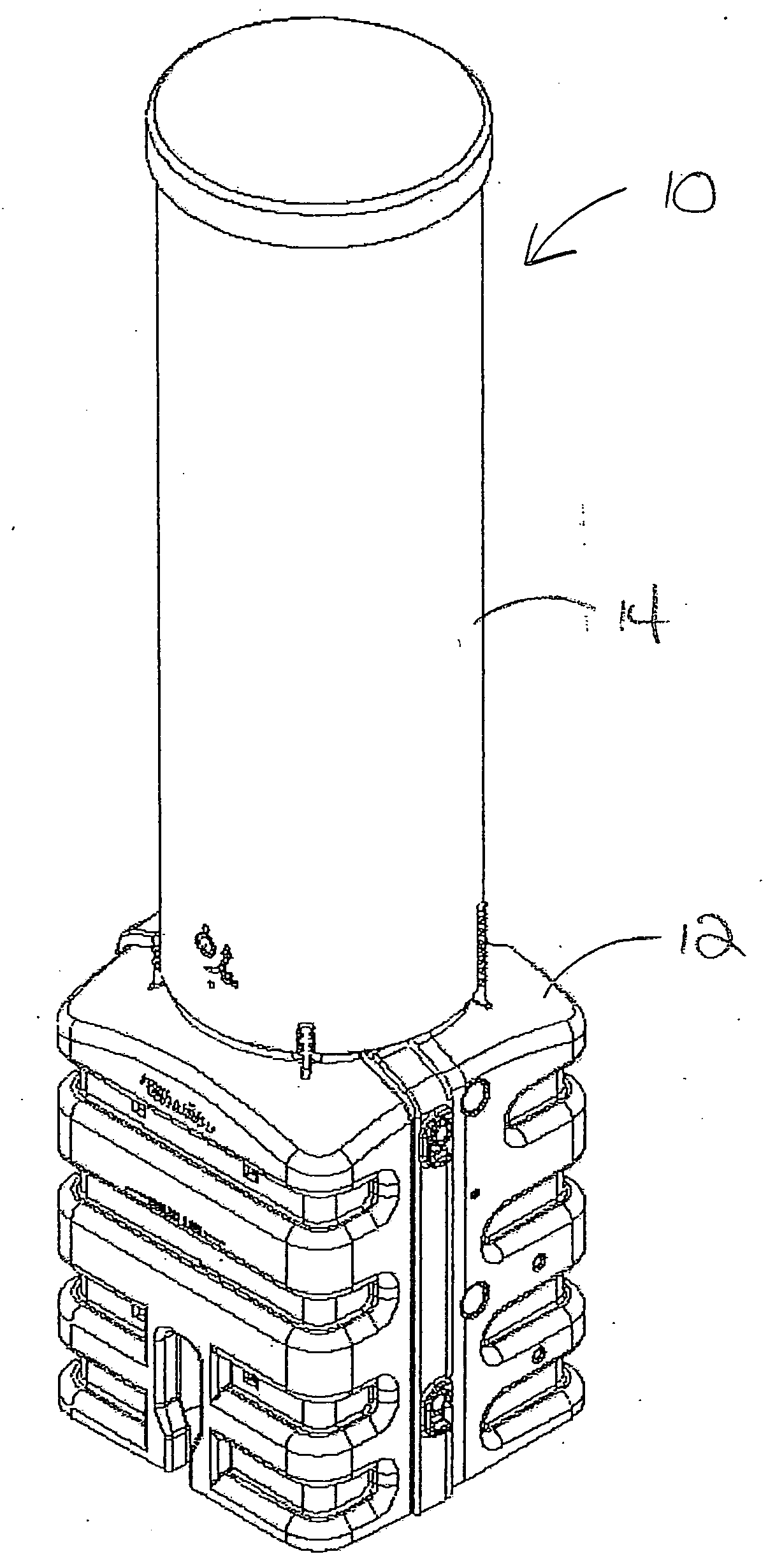
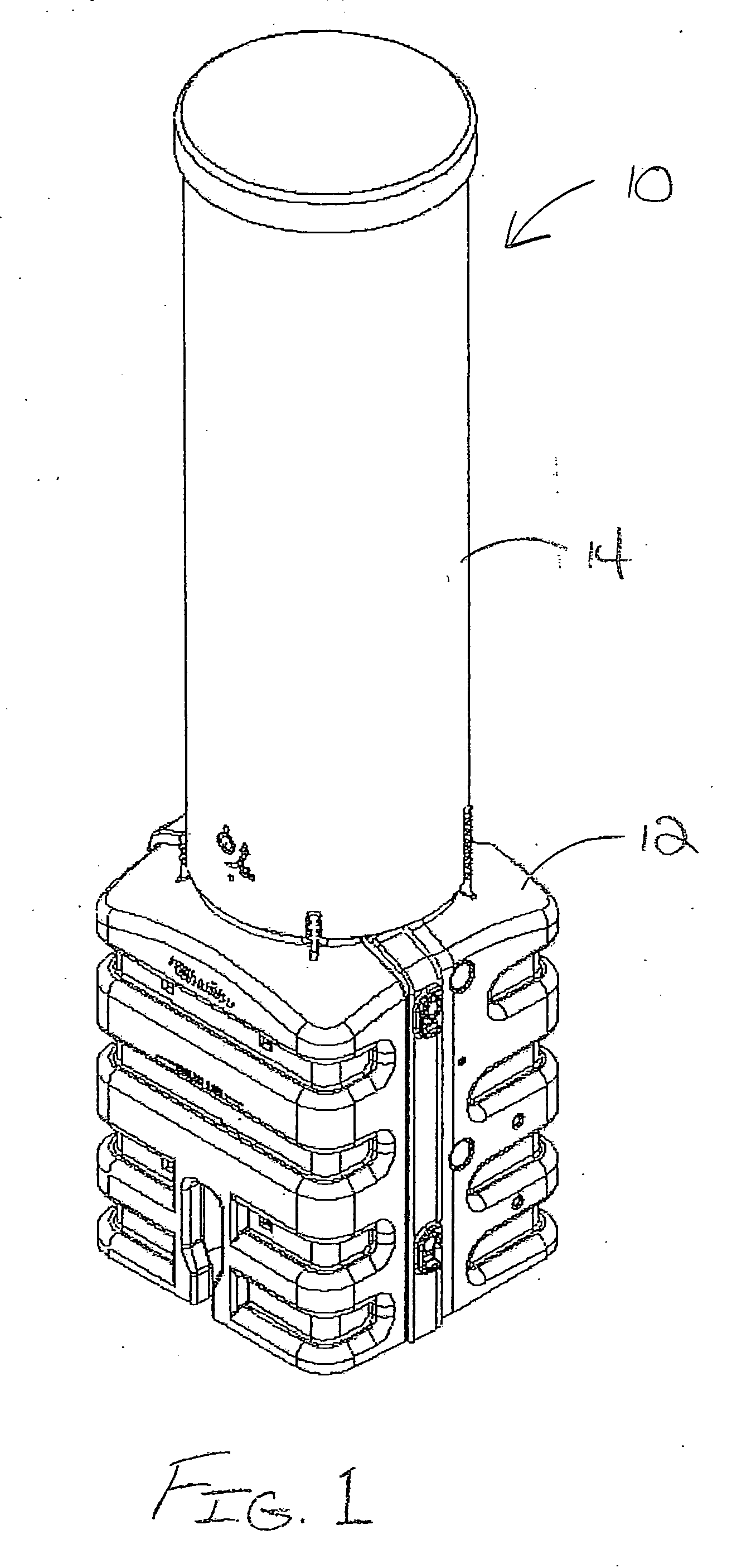
[0041]Referring now to FIG. 1 of the drawings, there is illustrated an exemplary fiber optic splice enclosure 10 constructed in accordance with the teachings of the present invention. The illustrated fiber optic splice enclosure 10 has a pedestal configuration that includes a base section 12 and a cover or dome 14. In this case, the cover 14 nests in a telescoping fashion over the base section 12 so as to define an interior space within the enclosure 10 that can house fiber optic splice connections and other telecommunications equipment. Inside the enclosure 10, the splices and other equipment are protected against damage from water, fire, wind-blown dust and debris and impact. When in-use, at least a portion of the base section 12 is typically filled with dirt and / or gravel and buried in the ground. Fiber optic cables can be fed into the interior space of the splice enclosure 10 through one or more openings in the base section 12.

[0042]The use of the pedestal configuration for the ...


PUM


Abstract

A fiber optic splice enclosure for housing an interconnection contained in a splice tray between at least one optical fiber of a feeder cable and at least one optical fiber of a drop cable is provided. The optical fiber of the feeder cable is at least partially contained in a feeder cable buffer or transportation tube. The fiber optic splice enclosure includes a support frame arranged in the enclosure. The support frame includes a central office side and a drop side. A basket is arranged on the support frame for storing slack of a spliced buffer tube transitioning to the splice tray. The spliced storage arrangement is sized so as to be able to store slack of the spliced feeder cable buffer tube while maintaining a predetermined tube bend radius. A splice tray mounting arrangement is arranged on the drop side of the support frame for supporting the splice tray.

Description

CROSS-REFERENCE TO RELATED APPLICATIONS[0001]This patent application claims the benefit of U.S. Provisional Patent Application No. 60 / 771,248, filed Feb. 8, 2006.FIELD OF THE INVENTION[0002]This invention pertains to enclosures for housing optical fiber interconnections at distribution points in a fiber optic network.BACKGROUND OF THE INVENTION[0003]There is an ever-increasing demand for high-speed or high-bandwidth communication channels for delivering high-speed data and video services. To meet this demand, telecommunications service providers are developing networks (sometimes referred to as outside plant networks) that extend the higher bandwidth of fiber optic components all the way to the end-user businesses and homes (referred to as premises). In such networks, there are distribution points where a distribution, feeder or branch cable is interconnected with one or more drop cables that are routed to the premises. At such distribution points, the side coming from the service p...

Claims


Application Information

Patent Timeline
IPC IPC(8): G02B6/00
CPCG02B6/4452G02B6/4442
Inventor WITTMEIER, DAVID A.FOURNIER, WADE K.PLESNIAK, JEFFREY A.HARWOOD, WALTERCLAUNCH, CARNEY P.
Owner CHARLES INDS
Why Eureka
Try Eureka