Electronic apparatus cooling system and electronic apparatus cooling system fabrication method

a cooling system and electronic equipment technology, applied in the direction of lighting and heating equipment, electric equipment casings/cabinets/drawers, instruments, etc., can solve the problems of difficult to keep a space large enough, difficult to rapidly increase the number of electronic equipment installations, and insufficient cooling of each server, etc., to achieve excellent cooling characteristics

Inactive Publication Date: 2016-01-14
NEC CORP
View PDF21 Cites 17 Cited by
  • Summary
  • Abstract
  • Description
  • Claims
  • Application Information

AI Technical Summary

Benefits of technology

[0016]According to the present invention, the electronic apparatus cooling system with excellent cooling characteristics and portability can be provided.

Problems solved by technology

However, it is difficult to rapidly increase the number of electronic apparatus installations owing to the installation space problem and the installation environment such as the problem concerning to an air conditioner or power supply.
However, it is difficult to keep a space enough to send cooling air from the air conditioner to each rack when the racks equipped with a large number of servers are installed in a small space of the ISO specification container.
Therefore, a short return which inhales exhaust of the server occurs and each server cannot be cooled sufficiently.
The problem that cooling electric power increases due to measures for the short return also occurs.

Method used


Image

  • Electronic apparatus cooling system and electronic apparatus cooling system fabrication method
  • Electronic apparatus cooling system and electronic apparatus cooling system fabrication method
  • Electronic apparatus cooling system and electronic apparatus cooling system fabrication method

Examples


exemplary embodiment 1

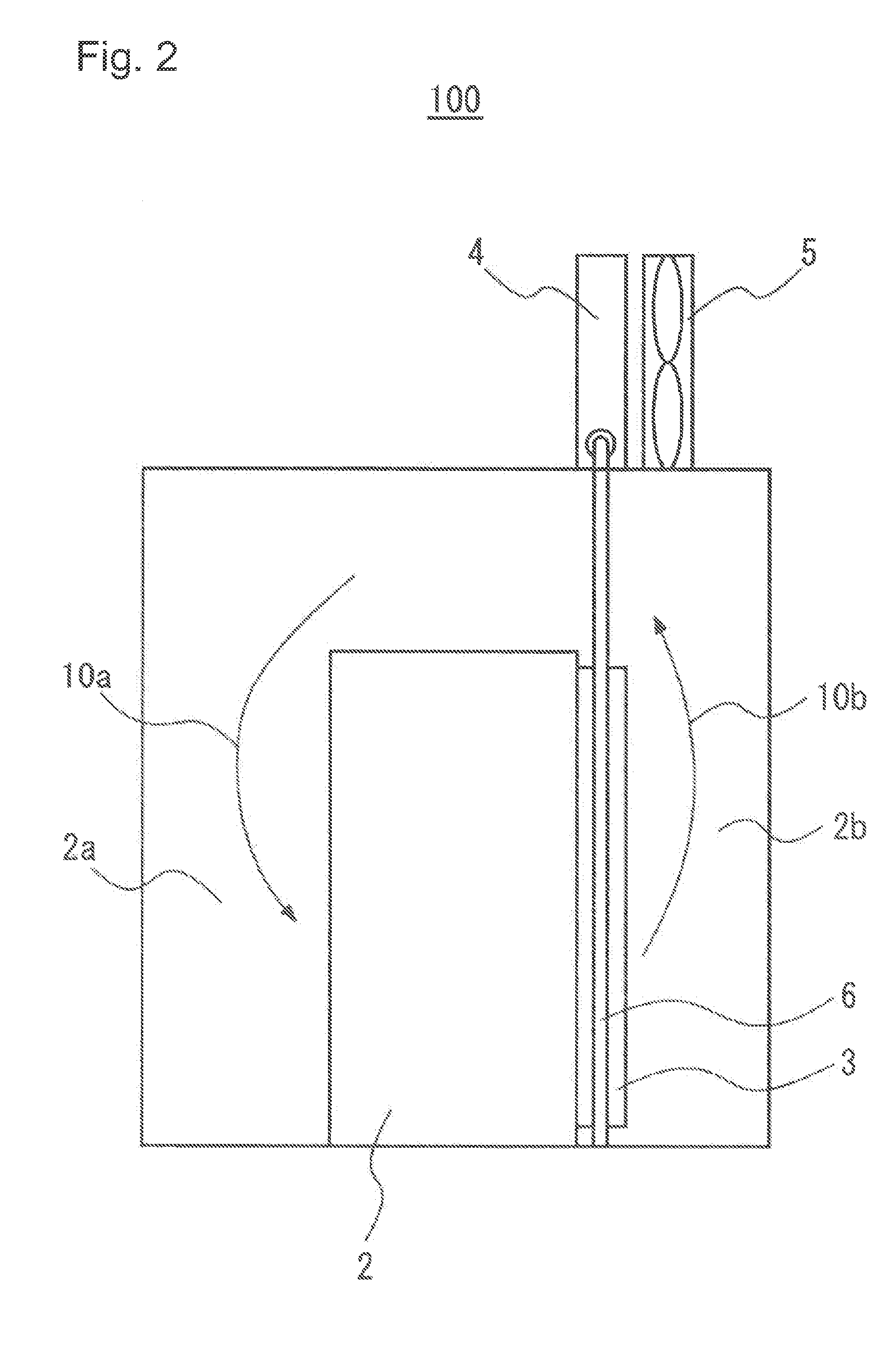
[0025]First, an electronic apparatus cooling system 100 according to an exemplary embodiment 1 is described. At below, although an electronic apparatus cooling system is constituted so as to be applied to a container type data center, for example, applicable objects are not limited to the container type data center. In addition, as the container size in the container type data center, the container with the size of 20 feet×8 feet×8 feet 6 inches or the half size capacity of 10 feet×8 feet×8 feet 6 inches of ISO (International Standardization Organization) is assumed. However, the size of the container is not limited to those. Moreover, although cases in which the container is employed are described below, it is applicable to not only the container but various vessels with portability and capability to store article therein.

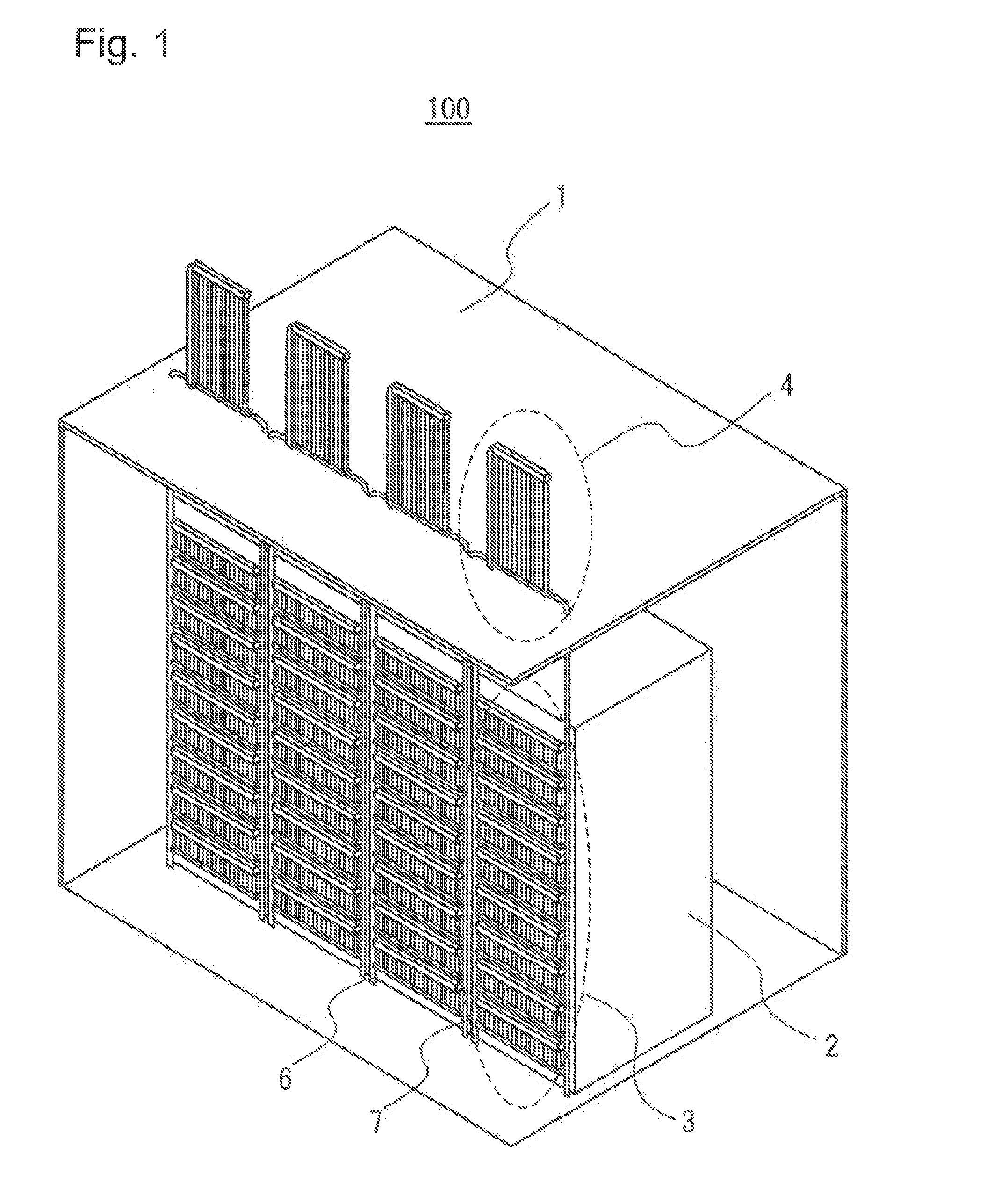
[0026]FIG. 1 is a perspective view which schematically indicates a structure of an electronic apparatus cooling system 100 according to the exemplary embodiment 1...

exemplary embodiment 2

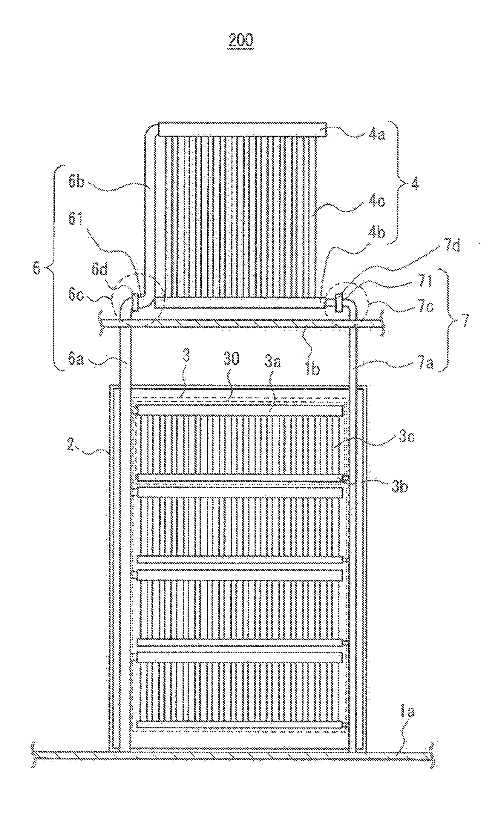
[0049]Next, an electronic apparatus cooling system 200 according to an exemplary embodiment 2 is described. The electronic apparatus cooling system 200 is modification of the electronic apparatus cooling system 100 according to the exemplary embodiment 1. FIG. 5 is a front view of a main portion of the electronic apparatus cooling system 200 according to the exemplary embodiment 2. The electronic apparatus cooling system 200 has a configuration in which a movable joint part 6d and a movable joint part 7d are added to the electronic apparatus cooling system 100.

[0050]The movable joint part 6d is inserted in the tube line 61 which extends in the horizontal direction in the vapor phase tube bend 6c. The movable joint part 6d is rotatably constituted in the axis direction which is the extension direction of the tube line 61 of the horizontal direction of the vapor phase tube bend 6c. Further, although the movable joint part 6d can employ a joint with a system which can rotate while seal...

exemplary embodiment 3

[0056]Next, an electronic apparatus cooling system 300 according to an exemplary embodiment 3 is described. The electronic apparatus cooling system 300 is modification of the electronic apparatus cooling system 200 according to the exemplary embodiment 1. FIG. 7 is a side view which schematically indicates a structure of the electronic apparatus cooling system 300 according to the exemplary embodiment 3. The electronic apparatus cooling system 300 has a configuration in which an air intake port 8 and an exhaust port 9 are added on a wall surface of the container 1 of the electronic apparatus cooling system 200. For example, an openable and closable louver can be used as the air intake port 8 and the exhaust port 9.

[0057]The air intake port 8 is installed on a wall surface in the side of the air intake side space 2a in the container 1. The open air of the container 1 is introduced in the container 1 through the air intake port 8. The exhaust port 9 is installed on a wall surface in t...


PUM

PropertyMeasurementUnit
sizeaaaaaaaaaa
sizeaaaaaaaaaa
cooling electric poweraaaaaaaaaa

Abstract

[Problem]To provide an electronic apparatus cooling system having superior cooling characteristics and portability.[Solution] A rack 2 is installed within a container 1. A heat receiving apparatus 3 is disposed on a lateral face of the rack 2, and receives heat emitted within the rack 2 by a liquid-phase cooling medium gasifying and becoming a gaseous-phase cooling medium. A gaseous-phase tube 6 is disposed extending in plumb direction, and transports the gaseous-phase cooling medium from the heat receiving apparatus 3. A heat radiating apparatus 4 is disposed above the rack 2 outside the container 1, and radiates the heat which the heat receiving apparatus 3 has received by cooling the gaseous-phase cooling medium flowing from the gaseous-phase tube 6, making said gaseous-phase cooling medium into the liquid-phase cooling medium. A liquid-phase tube 7 transports the liquid-phase cooling medium from the heat radiating apparatus 4 to the heat receiving apparatus 3. The gaseous-phase tube 6 further comprises a gaseous-phase tube bend part 6c whereat cooling medium droplets, which arise from the condensation of the gaseous phase cooling medium as a result of the gaseous-phase tube 6 being exposed to the environment external to the container 1, are collected.

Description

TECHNICAL FIELD [0001]The present invention relates to an electronic apparatus cooling system and a fabrication method of the electronic apparatus cooling system.BACKGROUND ART [0002]Recently, a great increase of information quantity has been expected along with development of information society. Due to the information increase, it becomes needed to install a plenty of electronic apparatus such as servers for information processing. However, it is difficult to rapidly increase the number of electronic apparatus installations owing to the installation space problem and the installation environment such as the problem concerning to an air conditioner or power supply.[0003]Accordingly, a modular type data center has been proposed which comprises equipment which adjusts an operation environment of the air conditioner or the like together with a rack in which a plenty of servers and network devices are equipped. As the modular type data center, for example, a container type data center ...

Claims


Application Information

Patent Timeline
Patent Type & Authority Applications(United States)
IPC IPC(8): H05K7/20B23P19/00
CPCH05K7/20818H05K7/20318H05K7/20327B23P19/00G06F1/20H05K7/20827F28D15/0266G06F2200/201
Inventor MATSUNAGA, ARIHIROYOSHIKAWA, MINORUSAKAMOTO, HITOSHICHIBA, MASAKISHOUJIGUCHI, AKIRAINABA, KENICHI
Owner NEC CORP
Why Eureka
Try Eureka