Rotary electric generator

A rotary and generator technology is applied in the field of cooling structures in the form of direct gas cooling of high-power rotary electric generators, and can solve the problems of easy explosion of hydrogen, increased overall cost of electric generator equipment, and inability to reduce unit prices.

Inactive Publication Date: 2003-12-17
HITACHI LTD
View PDF0 Cites 0 Cited by
  • Summary
  • Abstract
  • Description
  • Claims
  • Application Information

AI Technical Summary

Problems solved by technology

This has the disadvantage that the overall cost of the power generator equipment increases
Another problem is that hydrogen is an extremely explosive gas so extreme care must be taken in flammable environments including turbines
[0006] As mentioned above, although the above prior art can solve the problem of large capacity of power generators, there is a problem that the unit price per power output cannot be reduced

Method used


Image

  • Rotary electric generator
  • Rotary electric generator
  • Rotary electric generator

Examples


Embodiment Construction

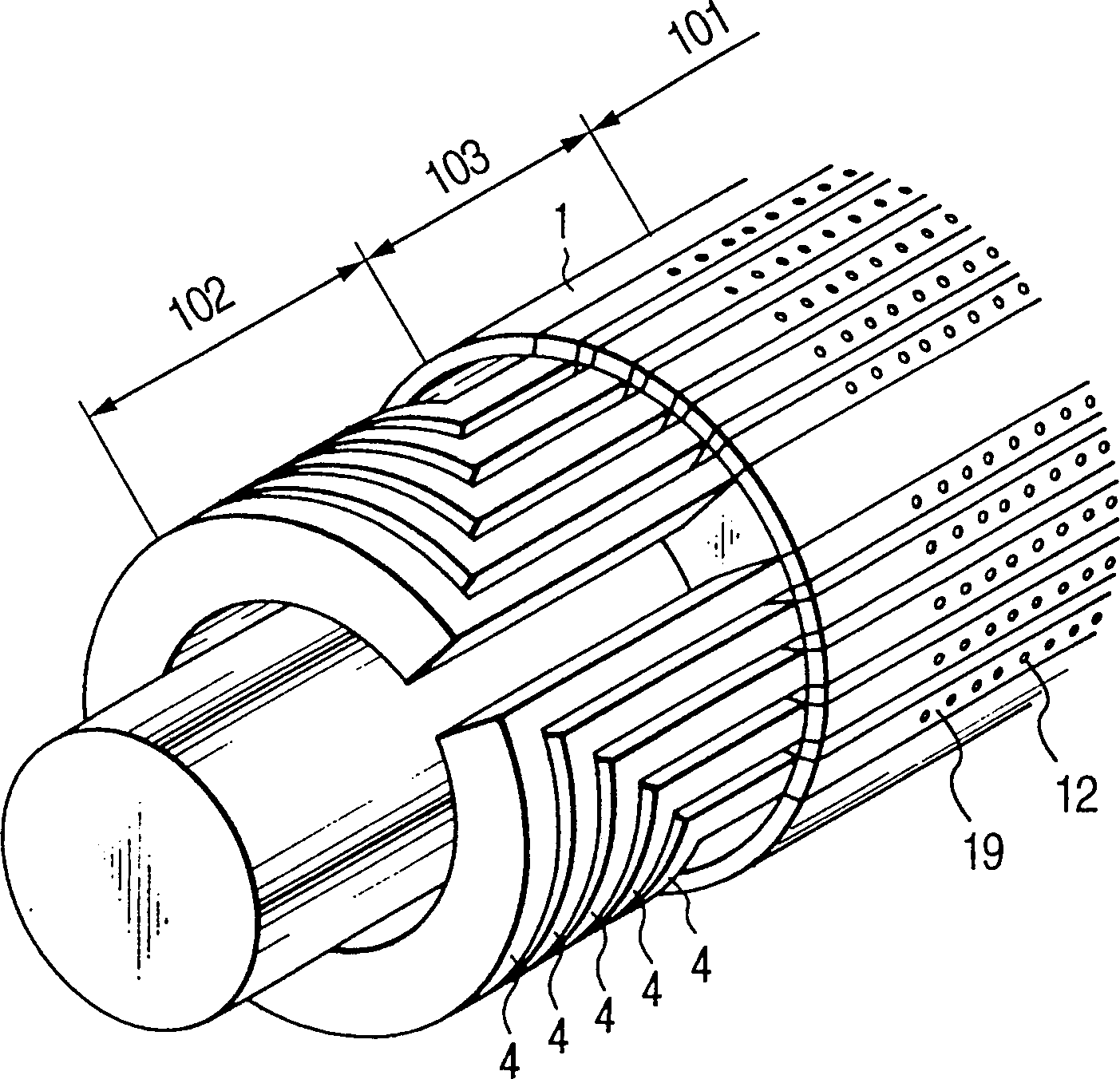
[0032] Before describing the embodiments of the present invention, the schematic structure of the turboelectric generator will be described. Fig. 1 is a schematic configuration diagram of an example of an air-cooled electric power generator using the present invention. However, the basic structure shown here does not depend on the type of cooling fluid.

[0033] In FIG. 1 , a rotor 1 is rotatably supported by a bearing 3 inside a stator 2 . In the rotor 1, a plurality of rotor windings 4 constituting the same magnetic pole are coaxially arranged around the magnetic pole, and are fixed. The centrifugal force exerted on the rotor winding 4 is supported at winding slots formed at intervals on the rotor circumferential surface with respect to the axial part, and is firmly supported at the guard ring 5 by the rotor end peripheral portion.

[0034] In the figure, although only one side of the slip ring 6 supplying current to the rotor is shown for convenience of explanation, there...


PUM


Abstract

A turbine electric power generator is provided with winding slots and sub-slots of a rotor; rotor windings having conductors and insulation materials laminated alternately thereon; wedges; and radial ventilation flow passages communicating the sub-slots with through holes of the wedges. In this turbine electric power generator, a projection is provided on an inner face of the radial ventilation flow passages, and the projection height is changed at a rotational axial position. In this manner, there can be provided a gas cooling type rotary electric power generator for turbine with its high cooling performance and high reliability at a low cost.

Description

technical field [0001] The present invention relates to a rotary electrical generator such as an electrical generator. In particular, the invention relates to cooling structures in the form of direct gas cooling of high power rotary electric generators. Background technique [0002] An electric generator, in particular a turboelectric generator, has a plurality of axially arranged rotor windings or axially formed slots in which the windings are arranged. These slots are arranged at certain intervals on the circumferential surface of the rotor main body on both sides of the magnetic pole part of the rotor main body, and a plurality of windings constituting the same magnetic pole are coaxially arranged around the magnetic pole. These windings consist of multiple turns of winding wire stacked radially with insulation between the turns. When power is applied to these windings from the outside, an electromagnetic field is generated on each pole. The winding is firmly fixed in ...

Claims


Application Information

Patent Timeline
Patent Type & Authority Patents(China)
IPC IPC(8): H02K1/32H02K3/24H02K9/06H02K9/16H02K15/04
CPCH02K3/24H02K15/0414H02K9/16
Inventor 森英明木枝茂和海保真行塩原亮一服部憲一
Owner HITACHI LTD
Why Eureka
Try Eureka