
Microsurgical instrument

a micro-screw and instrument technology, applied in the field of micro-surgical instruments, can solve the problems of large peak to peak fluctuation of intraocular pressure within the eye, unwanted turbulence of vitreous and retinal tissues, and the use of probes to perform mor

Inactive Publication Date: 2007-08-09
ALCON INC
View PDF35 Cites 201 Cited by
  • Summary
  • Abstract
  • Description
  • Claims
  • Application Information

AI Technical Summary

Problems solved by technology

In addition, these probes are also used to perform more delicate operations such as mobile tissue management (e.g. removing vitreous near a detached portion of the retina or a retinal tear), vitreous base dissection, and membrane removal.
However, the combined effect of large port size, large cut stroke, and relatively slow cut rate of these probes sometimes creates unwanted turbulence of the vitreous and retinal tissues and a large peak to peak fluctuation of intraocular pressure within the eye.
Both of these limitations cause difficulty for the surgeon and can be detrimental to the patient.
However, these probes are not highly effective for core vitrectomy, and thus the surgeon is often forced to use and repeatedly insert multiple vitrectomy probes within a patient's eye, complicating the surgery and increasing trauma to the patient.
However, it is believed that these probes are somewhat limited in flow rate, rendering them less effective for core vitrectomy.
Such adjustment is not practical or safe with the cutting tip of the probe disposed inside the eye.
In addition, such adjustment does not allow a surgeon to visualize the amount of open port adjustment with the cutting tip outside the eye because the operating microscope and associated lighting is set up to view the inside of the eye.
However, such a system is dependent on the pneumatic system used to drive the inner cutting member of the probe and is therefore subject to system pressure output variations.

Method used


Image

  • Microsurgical instrument
  • Microsurgical instrument
  • Microsurgical instrument

Examples


Embodiment Construction

[0019] The preferred embodiments of the present invention and their advantages are best understood by referring to FIGS. 1 through 6 of the drawings, like numerals being used for like and corresponding parts of the various drawings.

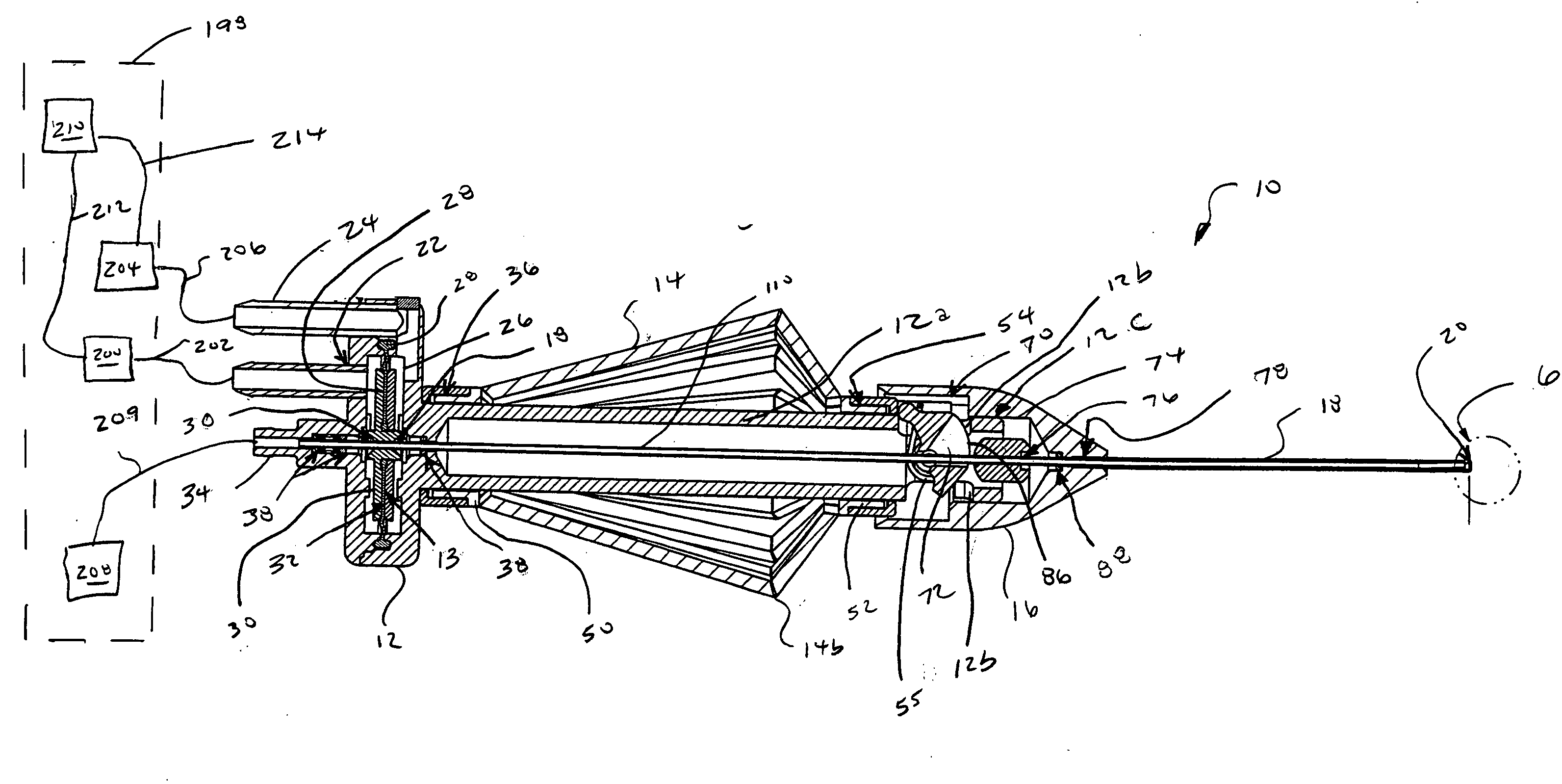
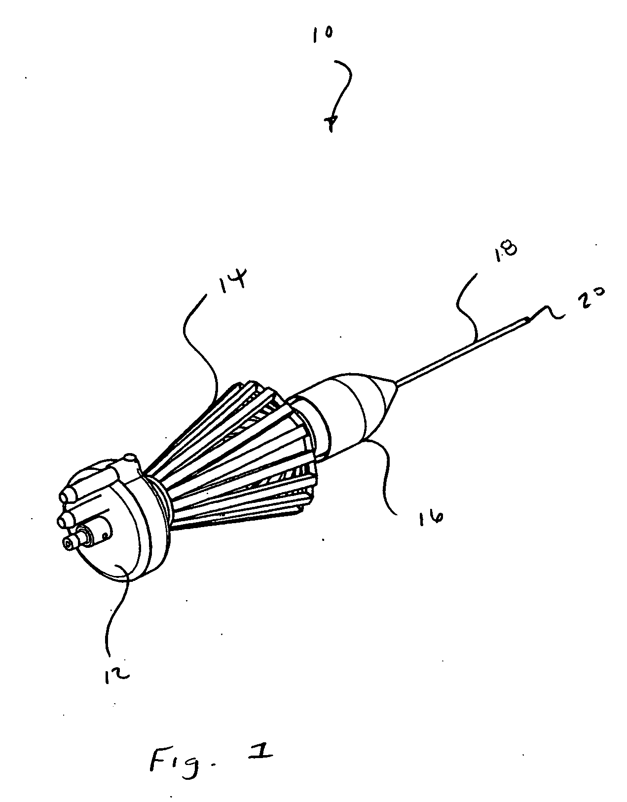
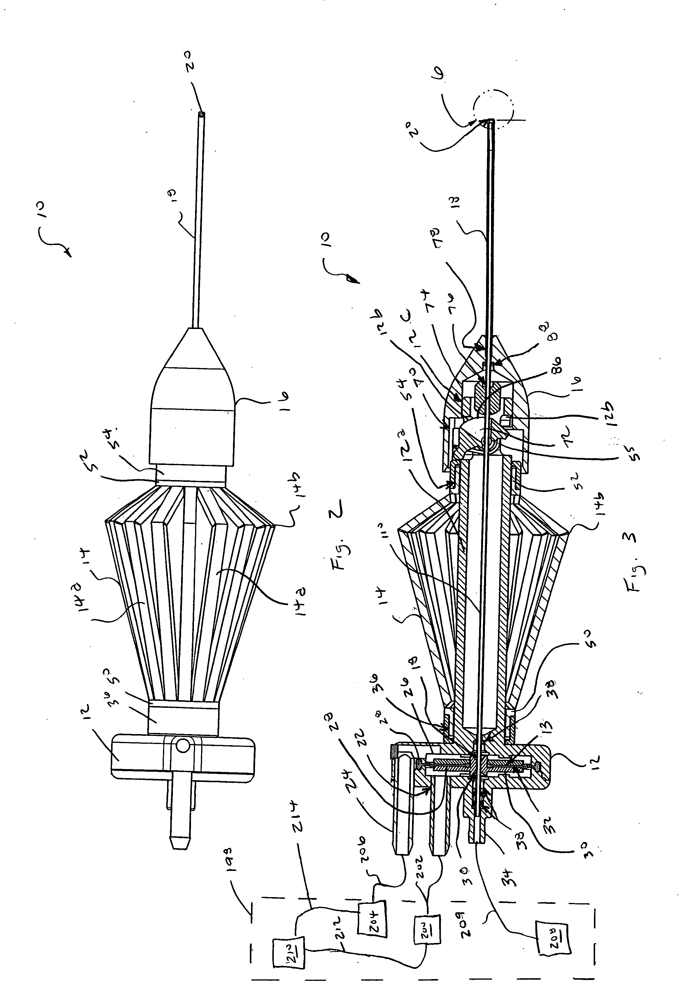
[0020] Microsurgical instrument 10 generally includes a base 12, an actuating handle 14, a nose member 16, and a cutting member 18 having a distal tip 20. As shown in the Figures, microsurgical instrument 10 is a vitrectomy probe. However, microsurgical instrument 10 may be any microsurgical cutting, aspiration, or infusion probe.

[0021] Base 12 includes an actuating mechanism 13 for actuating a tubular inner cutting member 110 of cutting member 18 in a reciprocating manner. Actuating mechanism 13 preferably includes a first pneumatic port 22, a second pneumatic port 24, a diaphragm chamber 26, a flexible diaphragm 28, and a rigid center support 30. Flexible diaphragm 28 is frictionally coupled to center support 30 and base 12. Base 12 further includes a...


PUM


Abstract

A microsurgical instrument including a cutting member, a base, a nose member, and an actuating handle providing the ability to safely adjust an open size of a port of the cutting member while the instrument is cutting tissue.

Description

FIELD OF THE INVENTION [0001] The present invention generally pertains to microsurgical instruments. More particularly, but not by way of limitation, the present invention pertains to microsurgical instruments having a port for aspirating and cutting tissue. DESCRIPTION OF THE RELATED ART [0002] Many microsurgical procedures require precision cutting and / or removal of various body tissues. For example, certain ophthalmic surgical procedures require the cutting and / or removal of the vitreous humor, a transparent jelly-like material that fills the posterior segment of the eye. The vitreous humor, or vitreous, is composed of numerous microscopic fibers that are often attached to the retina. Therefore, cutting and removal of the vitreous must be done with great care to avoid traction on the retina, the separation of the retina from the choroid, a retinal tear, or, in the worst case, cutting and removal of the retina itself. [0003] The use of microsurgical cutting probes in posterior seg...

Claims


Application Information

Patent Timeline
Patent Type & Authority Applications(United States)
IPC IPC(8): A61B17/32
CPCA61B17/32002A61B2017/00544A61F9/00763A61B2019/304A61B2017/2918A61B2090/034
Inventor KIRCHHEVEL, G. LAMAR
Owner ALCON INC
Features
  • Generate Ideas
  • Intellectual Property
  • Life Sciences
  • Materials
  • Tech Scout
  • Unparalleled Data Quality
  • Higher Quality Content
  • 60% Fewer Hallucinations
Learn More