
Securing network traffic using distributed key generation and dissemination over secure tunnels

Inactive Publication Date: 2007-08-09
CIPHEROPTICS
View PDF25 Cites 82 Cited by
  • Summary
  • Abstract
  • Description
  • Claims
  • Application Information

AI Technical Summary

Benefits of technology

[0038] In addition to the IPsec functionality, certain additions to the capacity of the Policy Enforcement Point may provide further flexibility:
[0076] In another embodiment, the PEPs may use shared keys to perform data decryption and encryption around firewalls, intrusion detection systems, SSL accelerators, and other devices that need to inspect decrypted packets, without burdening the network with multiple secure negotiations.

Problems solved by technology

Although IPsec tunnel mode has been used effectively in securing direct data links and small collections of gateways in networks, a number of practical limitations have acted as a barrier to more complete acceptance of IPsec as a primary security solution throughout the industry.
This is a challenge in terms of the user setting up the policies, the time required to load the policies, the memory and speed difficulties in implementing the policies, and the increase in network time spent performing negotiations and rekey.
Certificate / PKI Management—PKI can become complex and difficult to manage.
At a minimum, it is intimidating to many network managers, however, strong PKI implementation is at the heart of effective security using IPsec (or TLS for that matter).
Multicast / Broadcast Traffic—IPsec in its present configuration cannot secure multicast or broadcast traffic.
The IETF has a couple of RFCs in place or in process to address this (GDOI, GSAKMP), but they are addressed only to multicast and require the implementation of a multicast network to distribute keys, and are not yet generally available.
If a set of SGW units must be placed along these parallel paths, there may be no way to assure which SGW the traffic sees.
This is not possible in existing IPsec implementations.
The result is a limitation in the placement of SGW units in the network which may not be possible in certain situations.
Network Address Translation (NAT)—There are various forms of NAT, all of which cause problems for IPsec.
This would likely create problems on the receiving network or on the return packet.
Unfortunately, if the SGW is behind the NAT device, IPsec hides the port and IP address on the original packet and does not provide a port on the outer header.
Many firewall functions can be implemented using well written IPsec policies, although this can complicate the SPD entries.
If the devices behind the SGW uses the largest packet size, the SGW must either fragment the packet, which can be slow and certainly reduces network efficiency, or ignore the PMTU.
This can be accomplished with VRRP, but a switch-over would result in the need to rekey all traffic.
In a fully meshed situation, this could be a significant interruption.
One of the most significant barriers to general acceptance of IPsec as a security solution is the challenge of securing data from where it leaves one computer to where it enters another computer.
Some of the general limitations of IPsec are exacerbated by end-to-end deployment.
For example, the IPsec implementation cannot be placed on the WAN side of the firewall, IDS, NAT device, or any load balancing between virtual servers.
There are a number of hurdles to true end-to-end security in addition to the general limitations described above.
Hardware solutions, such as IPsec on a NIC, provide some separation from these issues, but preclude automated remote installation of the IPsec stack.
Ideally, the user would be identified in some way other than a machine based certificate, but unfortunately, all existing implementations require the computer to be configured directly, normally by a network security manager.
A software solution on a computer (or mobile device) would be unable to provide high speed encryption or latency as low as on the existing SGW.
In some cases this does not matter, but in situations with a high speed connection or involving streaming data, this may be significant.
A hardware solution may suffer this limitation as well due to heat, space, or power considerations.
Either solution may be limited in the number of SAs or policies that are supported, and could be critical in a large meshed security situation.

Method used


Image

  • Securing network traffic using distributed key generation and dissemination over secure tunnels
  • Securing network traffic using distributed key generation and dissemination over secure tunnels
  • Securing network traffic using distributed key generation and dissemination over secure tunnels

Examples


Embodiment Construction

[0089] A description of preferred embodiments of the invention follows.

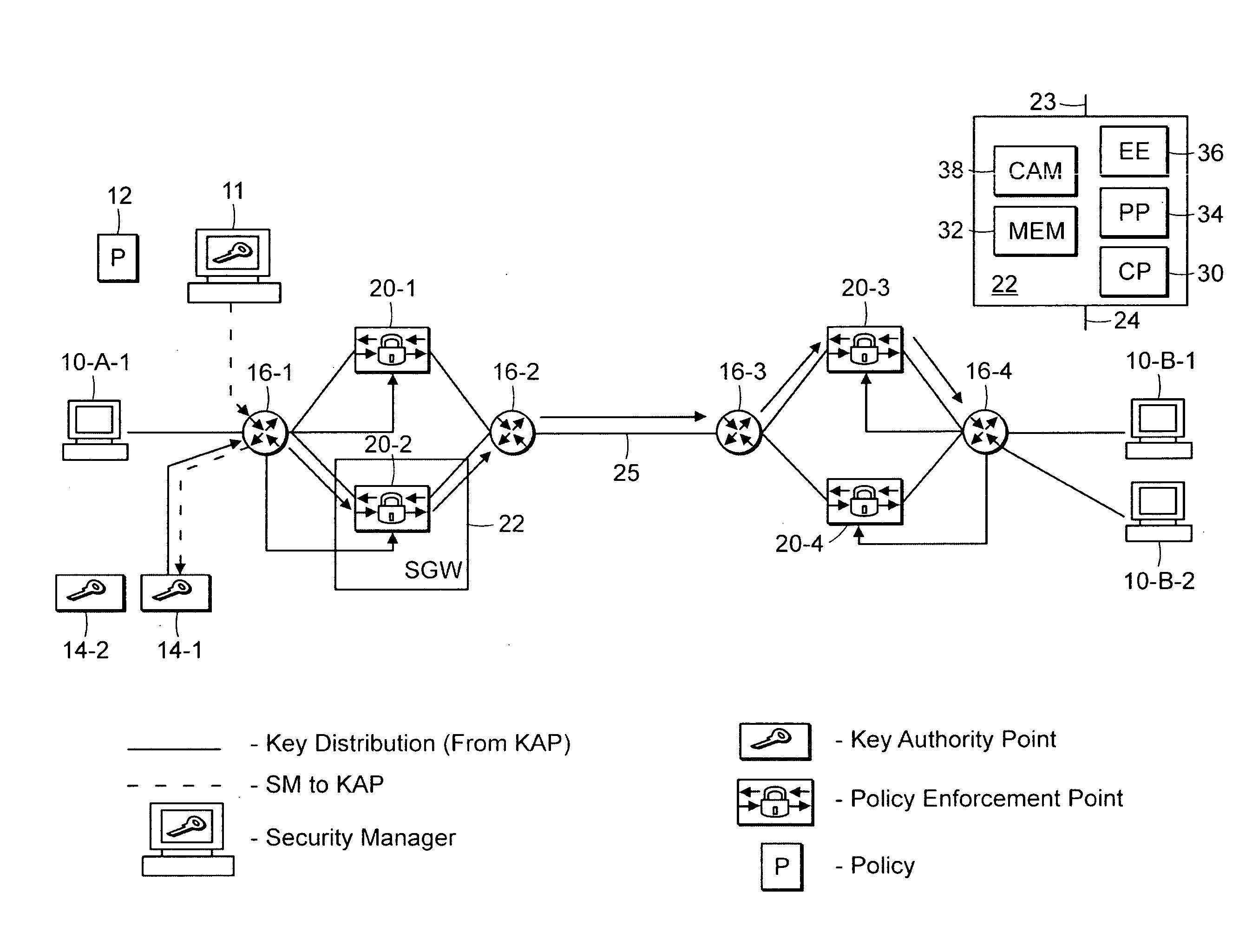
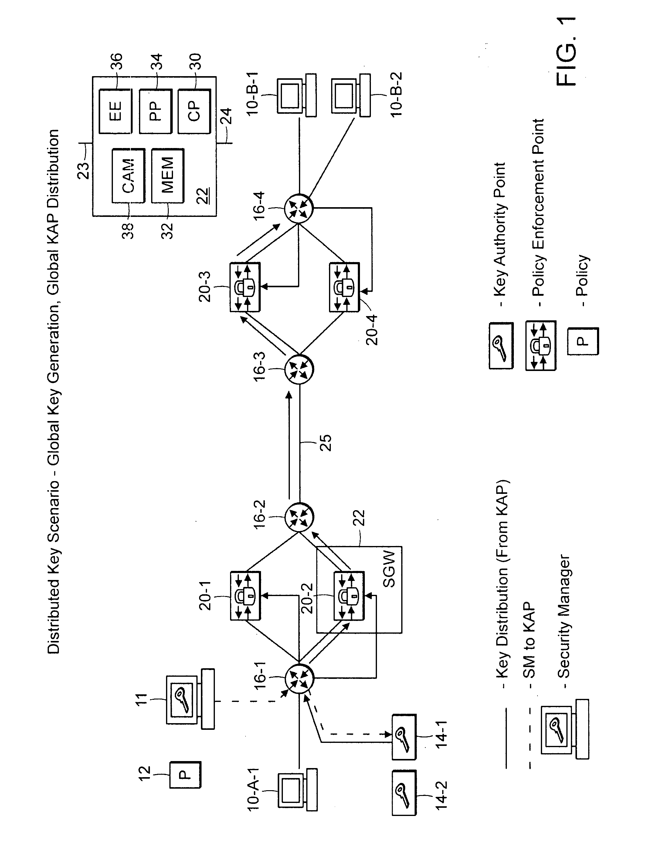
[0090]FIG. 1 is a system level diagram of a scheme for securing message traffic in a network in which a key is generated and then distributed through the network according to the invention.

[0091] The system generally includes a number of data processors and data processing functions including end nodes 10, a Management and Policy Server (MAP) 11, a Key Authority Point (KAP) 14, at least two inter-networking devices 16, such as routers / switches, and Secure Gateways (SGWs) 22. A secure tunnel connection 25 is maintained between at least two SGWs 22. The secure tunnel 25 can be provided by Secure Sockets Layer (SSL) and / or Transport Layer Security (TLS) or by a number of other known ways. Additionally, one or more of the SGWs 22 has an associated Policy Enforcement Point (PEP) function 20. It should be understood that other functions and devices may be present in the network and the above configuration is only one...


PUM


Abstract

A technique for securing message traffic in a data network using a protocol such as IPsec, and more particularly various methods for distributing security keys where key generation, key distribution, policy generation and policy distribution are separated, with inner to outer header replication on packet traffic. The approach permits encrypted messages to travel seamlessly through various otherwise unsecured internetworking devices.

Description

RELATED APPLICATION [0001] This application claims the benefit of U.S. Provisional Application No. 60 / 756,765, filed on Jan. 6, 2006. The entire teachings of the above referenced application are incorporated herein by reference.BACKGROUND OF THE INVENTION [0002] The present invention relates to securing message traffic in a data network using a protocol such as IPsec, and relates more particularly to how security keys are distributed, with inner to outer header replication on packet traffic, so that secure packets may travel seamlessly through various otherwise unsecured internetworking device configurations. [0003] The following definitions are used in this document: [0004]“Securing” implies both encryption of data in transit as well as authenticating that the data has not been manipulated in transit. [0005] A “secure tunnel” between two devices ensures that data passing between the devices is secure. [0006] A “security policy” (or “policy”) defines data (or “traffic”) to be secure...

Claims


Application Information

Patent Timeline
IPC IPC(8): G06F15/16G06F17/00G06F9/00
CPCH04L63/20H04L63/164
Inventor MCALISTER, DONALD K.
Owner CIPHEROPTICS
Features
  • Generate Ideas
  • Intellectual Property
  • Life Sciences
  • Materials
  • Tech Scout
  • Unparalleled Data Quality
  • Higher Quality Content
  • 60% Fewer Hallucinations
Learn More