Accessory

Inactive Publication Date: 2007-08-16
CROSSFOR
View PDF11 Cites 0 Cited by
  • Summary
  • Abstract
  • Description
  • Claims
  • Application Information

AI Technical Summary

Benefits of technology

[0014]With the accessory according to the present invention, the insertion hole part corresponding to the shapes of the stop part and the insertion core part extending from the stop part by the predetermined length are comprised, and the stop part is fixed to the catch made of an elastic material, whereby the stop part is easy to be inserted into the catch and difficult to fall. A

Problems solved by technology

If the diameter of the stop part is made larger than the accessory core part in order to prevent this fall, there arises a problem such that the wearing target is injured, or the pierced earring does not become stable in the wearing target.
Additionally, since the stop part has a protruding configuration, for example,

Method used


Image

  • Accessory
  • Accessory
  • Accessory

Examples


Embodiment Construction

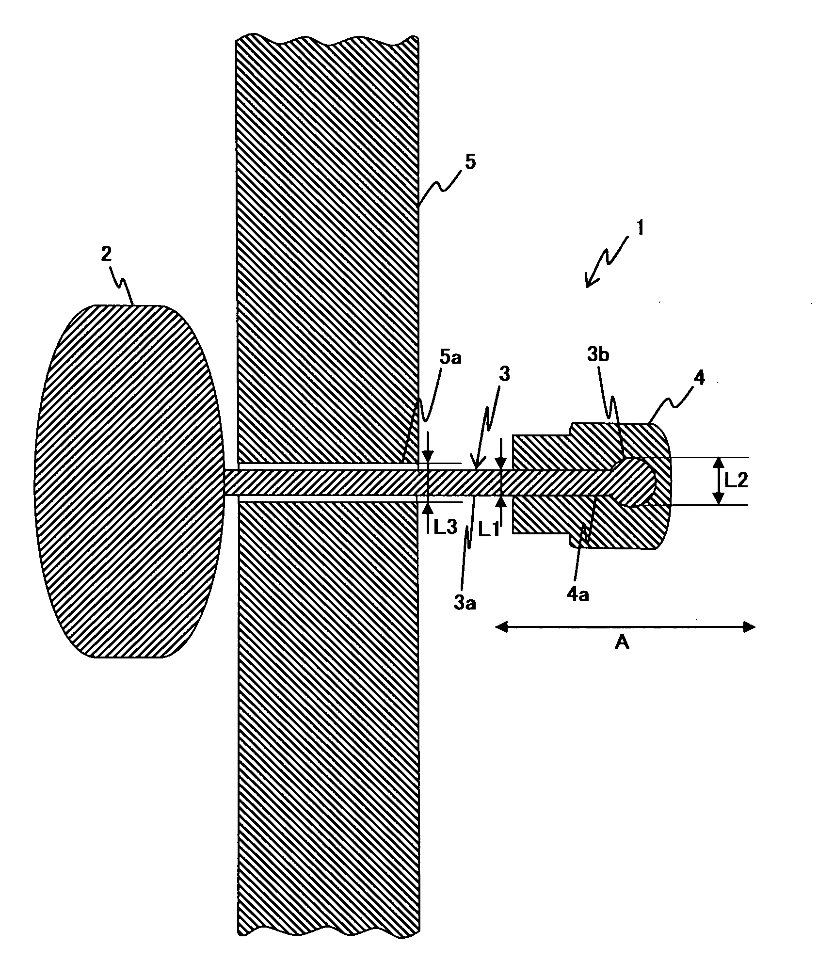
[0021]An accessory according to a preferred embodiment of the present invention is hereinafter described with reference to the drawings.

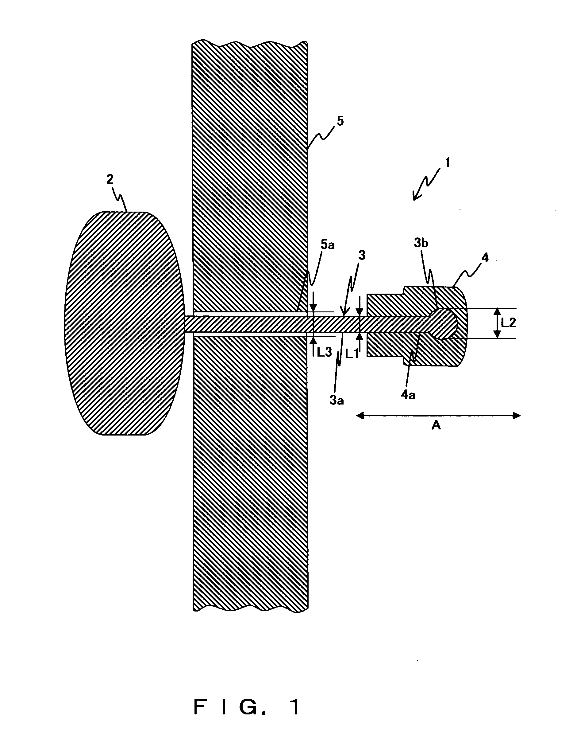
[0022]FIG. 1 is a cross-sectional view showing the accessory according to one preferred embodiment of the present invention.

[0023]In this figure, the accessory 1 comprises a basic accessory part 2, an insertion part 3, and a catch 4. This accessory 1 is inserted into a penetration hole 5a provided in a wearing target 5. The basic accessory part 2 is an accessory portion, which is positioned on the front side of the wearing target 5, namely, positioned in a portion that is most visible in the accessory 1.

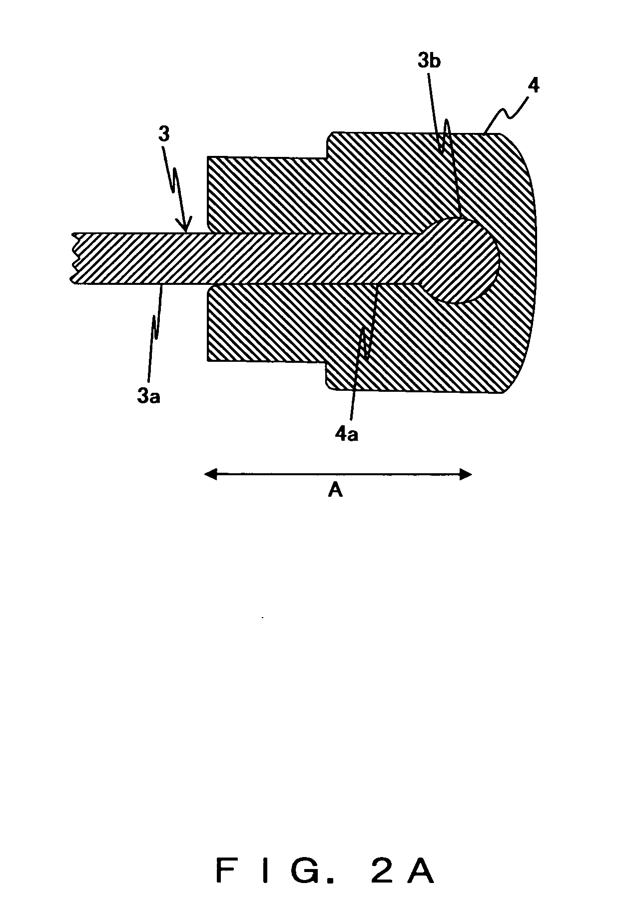
[0024]The insertion part 3 comprises an insertion core part 3a and a stop part 3b. One end of the insertion core part 3a is joined to the basic accessory part 2, for example, by being formed as a single-piece or by being welded. In contrast, the stop part 3b, which has a diameter L2 larger than the diameter L1 of the insertion core part 3a on a plane...


PUM


Abstract

In an accessory comprising a basic accessory part, an insertion part, which is joined to the basic accessory part and inserted into a penetration hole provided in a wearing target, and a catch for holding a portion of the insertion part, which penetrates into the penetration hole, the insertion part comprises an insertion core part one end of which is joined to the basic accessory part, and a stop part which is formed at the other end of the insertion core part and has a diameter larger than the insertion core part on a plane orthogonal to the longitudinal direction of the insertion core part, and the catch is made of an elastic material and has an insertion hole corresponding to the shapes of the stop part and a portion of the insertion core part extending from the stop part by a predetermined length.

Description

BACKGROUND OF THE INVENTION[0001]1. Field of the Invention[0002]The present invention relates to an accessory put on a human earlobe, etc.[0003]2. Description of the Related Art[0004]Conventionally, accessories such as pierced earrings are configured by joining an accessory core part (such as a needle) to a basic accessory part, and a portion of the accessory core part, which penetrates into a wearing target (such as an earlobe), is held by a catch in normal cases. Here, holding by a normal catch is made to prevent the accessory core part from falling out of the wearing target.[0005]For the above described accessory, the following accessory is disclosed, for example, by Patent Document 1 (Japanese Examined Utility Model Application Publication No. HEI7-6809). This accessory is configured by providing a basic accessory part having a diameter larger than that of the accessory core part at one end of the accessory core part, and a stop part also having a diameter larger than that of th...

Claims


Application Information

Patent Timeline
IPC IPC(8): A44B9/10
CPCY10T24/4616A44C7/003A44D2200/10
Inventor DOBASHI, HIDETAKA
Owner CROSSFOR
Why Eureka
Try Eureka