Torque detection device

a detection device and torque technology, applied in the direction of measurement devices, instruments, work measurement, etc., can solve the problems of tubular magnet cracking, etc., and achieve the effect of improving the torque detection device and reducing the number of steps

Active Publication Date: 2007-08-16
JTEKT CORP +1
View PDF8 Cites 1 Cited by
  • Summary
  • Abstract
  • Description
  • Claims
  • Application Information

AI Technical Summary

Benefits of technology

[0008] The torque detection device constructed in this manner can reduce the number of steps required for the assembly of the tubular magnet 101. However, when the molding is carried out in the cavity, the molding pressure of the molten synthetic resin material injected in the cavity is applied to an inner circumferential face of the tubular magnet 101, and due to this molding pressure, a crack might occur in the tubular magnet 101. Therefore, the measures to further improve the torque detection device have been desired.
[0009] The present invention has been made in view of the above-described problems, and its main object is to provide a torque detection device that can prevent a tubular magnet, fixed to a rotating body by molding, from being cracked due to a molding pressure.

Problems solved by technology

However, when the molding is carried out in the cavity, the molding pressure of the molten synthetic resin material injected in the cavity is applied to an inner circumferential face of the tubular magnet 101, and due to this molding pressure, a crack might occur in the tubular magnet 101.

Method used


Image

  • Torque detection device
  • Torque detection device
  • Torque detection device

Examples


embodiment 1

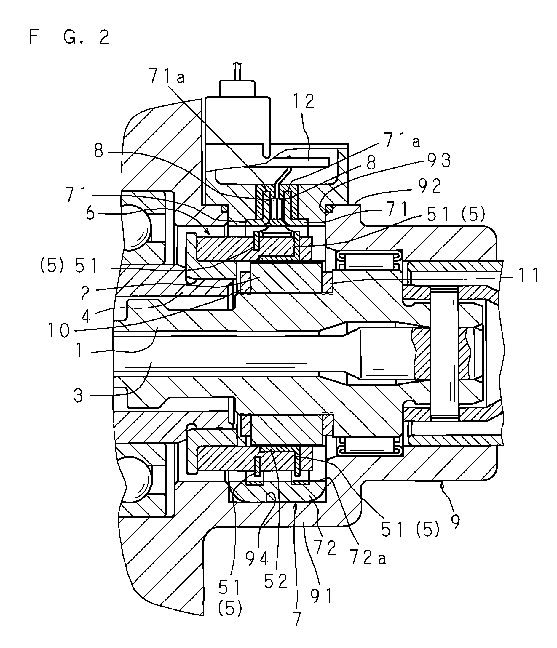
[0029]FIG. 2 is a cross-sectional view of a torque detection device according to the present invention, inserted into a housing. FIG. 3 is a perspective view of the inventive torque detection device. FIG. 4 is a schematic exploded perspective view of the inventive torque detection device. FIG. 5 is a diagram for describing a magnetic circuit generated when a rotating body is rotated in one direction. And FIG. 6 is an enlarged cross-sectional view of a principal part of the inventive torque detection device.

[0030] An inventive torque detection device includes: a magnetic circuit forming member 6 having a tubular magnet 2 externally fitted and fixed to an outer circumferential portion of a first rotating body 1, and two magnetic rings 5, 5 that are located circumferentially of the tubular magnet 2 and rotated together with a second rotating body 4 connected coaxially with the first rotating body 1 via a torsion bar 3; a magnetic flux collecting ring part 7 for collecting a magnetic f...

embodiment 2

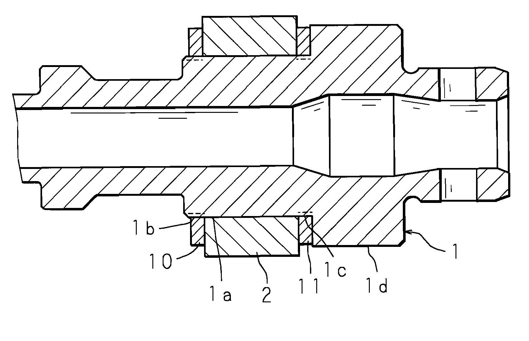
[0039]FIG. 7 is an enlarged cross-sectional view showing the constitution of a principal part of a torque detection device according to the present invention. In this torque detection device, outer edges of both ends of the tubular magnet 2 are chamfered to provide chamfered portions 2a, 2a, and the first and second molded bodies 10 and 11 are joined to the two chamfered portions 2a, 2a.

[0040] In Embodiment 2, since a molding pressure generated in a cavity can be applied to the longitudinal both ends of the tubular magnet 2 and to the chamfered portions 2a, 2a of the outer edges, the molding pressure applied to the tubular magnet 2 can be distributed in the longitudinal direction thereof, and radially inward in the direction intersecting the longitudinal direction, thus making it harder for the tubular magnet 2 to be cracked due to the molding pressure.

[0041] Other constitutions and operations are the same as in Embodiment 1; therefore, the same components are identified by the sa...

embodiment 3

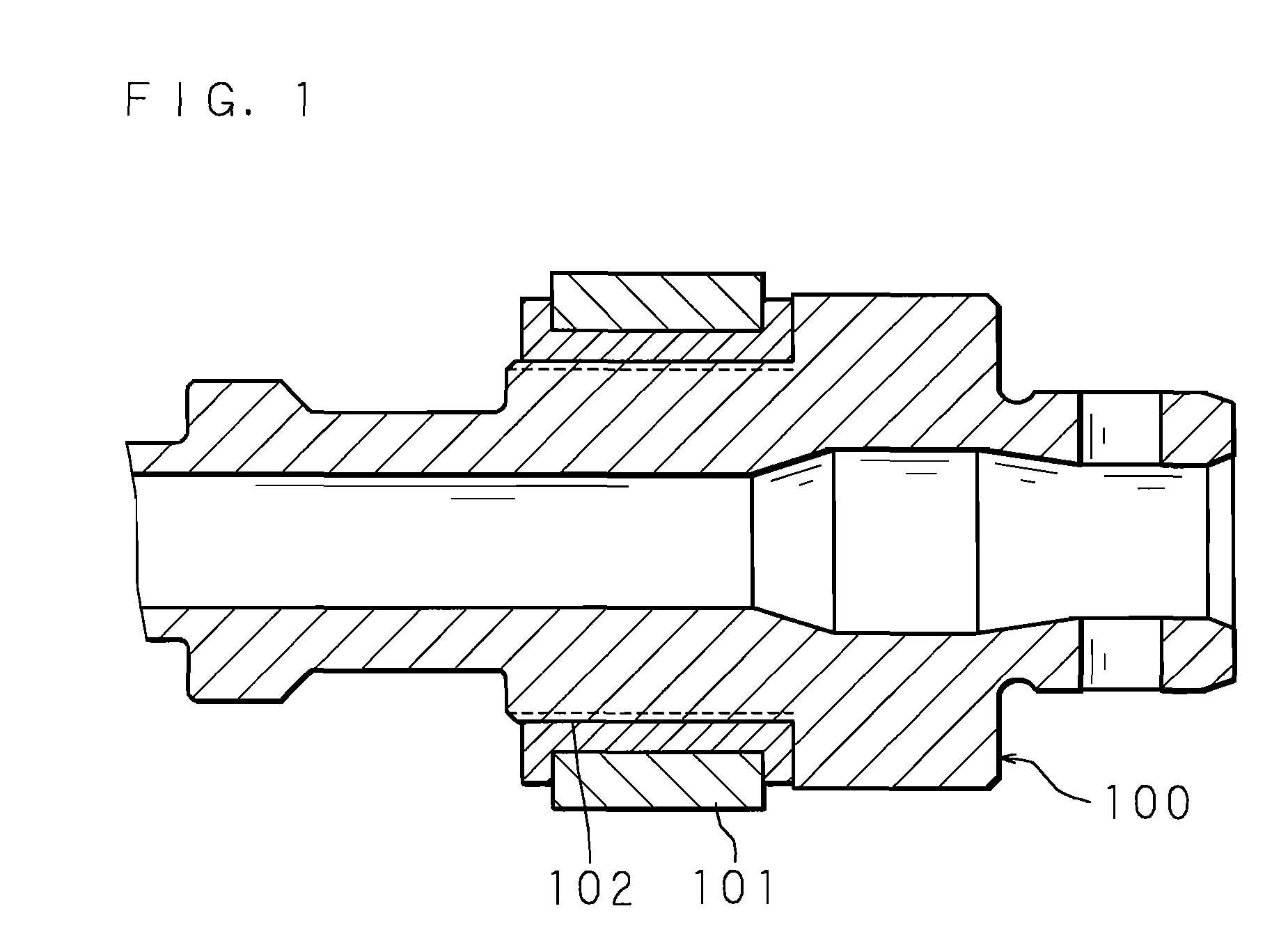
[0042]FIG. 8 is an enlarged cross-sectional view showing the constitution of a principal part of a torque detection device according to the present invention. In this torque detection device, the second rotation preventing portion 1c and the second molded body 11 according to Embodiment 1 are not provided, and the first molded body 10 is provided on longitudinal one end of the tubular magnet 2 so that the other end of the tubular magnet 2 is abutted against a step of the second fitting portion 1d.

[0043] In Embodiment 3, a molding pressure generated in a cavity can be applied to longitudinal one side of the tubular magnet 2, the molding pressure applied to the tubular magnet 2 can be reduced, and the cracking of the tubular magnet 2 due to the molding pressure can be further reduced.

[0044] Other constitutions and operations are the same as in Embodiment 1; therefore, the same components are identified by the same reference numerals, and the detailed description thereof and the desc...


PUM

PropertyMeasurementUnit
magnetic fluxaaaaaaaaaa
densityaaaaaaaaaa
torqueaaaaaaaaaa

Abstract

An inventive torque detection device includes: a magnetic circuit forming member having a tubular magnet provided at a first rotating body, and a magnetic ring that is located circumferentially of the tubular magnet and rotated together with a second rotating body connected to the first rotating body; a magnetic flux collecting ring part for collecting a generated magnetic flux; a detection part for detecting, based on a density of the collected magnetic flux, a torque applied to the first or second rotating body; and a molded body that is molded at an outer circumferential portion of the first rotating body, and is joined to longitudinal both sides of the tubular magnet so as to fix the tubular magnet to the first rotating body. A molding pressure, generated when the tubular magnet is molded, is applied in the longitudinal direction of the tubular magnet.

Description

CROSS-REFERENCE TO RELATED APPLICATIONS [0001] This Nonprovisional application claims priority under 35 U.S.C. §119(a) on Patent Application No. 2006-023774 filed in Japan on Jan. 31, 2006, the entire contents of which are hereby incorporated by reference. BACKGROUND OF THE INVENTION [0002] The present invention relates to a torque detection device for detecting a torque applied to a rotating body. [0003] An exemplary torque detection device is disclosed in Japanese Patent Application Laid-Open No. 2005-69994 (which will be hereinafter simply called “conventional example”), for example. The torque detection device according to the conventional example includes: a magnetic circuit forming member having a tubular magnet provided at either one of input and output shafts connected via a torsion bar, and a magnetic ring that is located circumferentially of the tubular magnet and rotated together with the other one of the input and output shafts; a magnetic flux collecting ring part for c...

Claims


Application Information

Patent Timeline
Patent Type & Authority Applications(United States)
IPC IPC(8): G01L3/00
CPCG01L3/104G01L5/22
Inventor TOKUMOTO, YOSHITOMOTAKAYAMA, SHINGONOZAKI, MIKIONAKANE, NAOKI
Owner JTEKT CORP
Why Eureka
Try Eureka