Adjustable wall hanger assembly

Active Publication Date: 2007-08-16
PRICE CORY D
View PDF15 Cites 14 Cited by
  • Summary
  • Abstract
  • Description
  • Claims
  • Application Information

AI Technical Summary

Benefits of technology

[0022] The clip bracket or bracket assembly is preferably C-shaped in cross section and comprises a main bracket body, a hanger pocket, a flexible snap arm, and means for fastening the clip bracket to a target wall-hanging such as certain fasteners or screws as well as fastener-receiving apertures. As fastened to the target wall-hanging, the clip bracket assembly and the wall-hanging thus form a bracketed wall-hanging. The hanger pocket functions to slidably receive the hanger tab for enabling

Problems solved by technology

It may be seen from an inspection of the noted prior art that the same does not disclose the unique structural configurations possessed by my vertically and horizontally adjustable wall hanger device for adjustably suspending a photograph

Method used


Image

  • Adjustable wall hanger assembly
  • Adjustable wall hanger assembly
  • Adjustable wall hanger assembly

Examples


Embodiment Construction

)

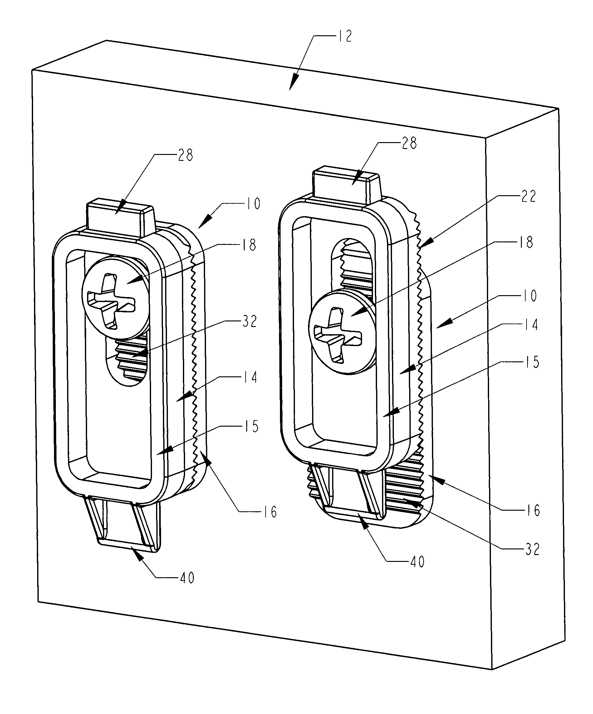
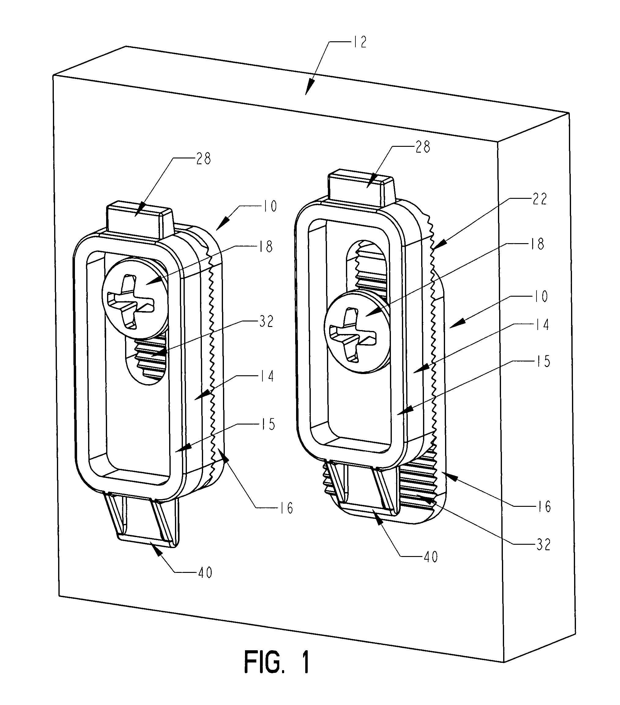
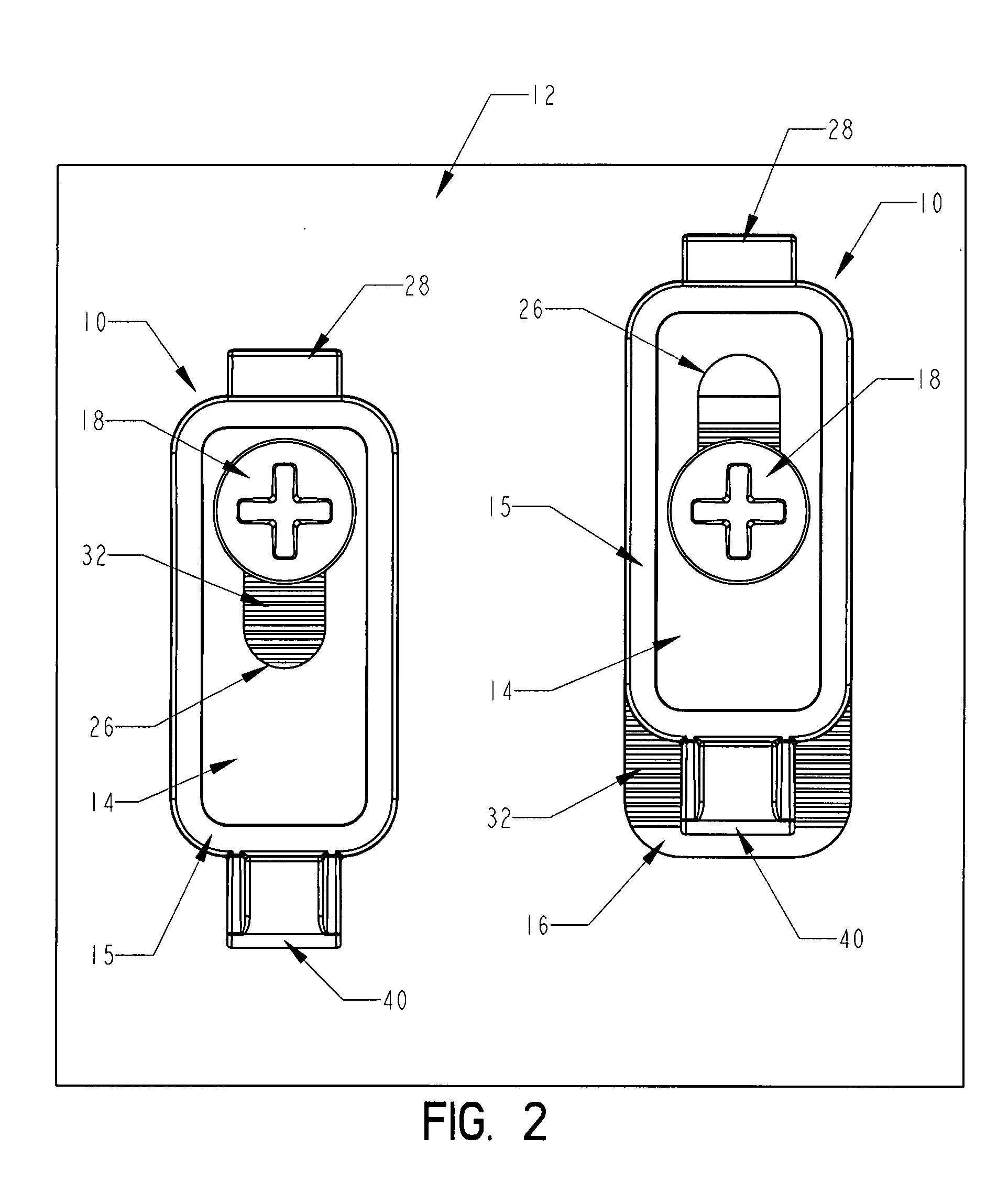
[0058] Referring now to the drawings with more specificity, the preferred practice of the present invention generally involves or concerns a new and improved adjustable wall-hanging assembly or hanger assembly 10 as generally illustrated and referenced in Figure Nos. 1-5, 16-22, and 28. It is contemplated that this hanger assembly 10 is adapted for hanging pictures, photographs, mirrors, and paintings and other assorted articles where it is desired to mount the same on a wall 12 as generally illustrated and referenced in Figure Nos. 1, 2, and 16-20). The noted figures generally illustrate and depict the hanger assembly 10 of the present invention. Figure Nos. 16-19 generally illustrate and depict how the adjustable hanger assembly 10 of the present invention may be effectively adjusted.

[0059] The adjustable hanger or hanger assembly of the present invention may be said to preferably comprise three parts, namely, a dish-shaped hanger 14 as illustrated and referenced in Figure Nos. ...


PUM


Abstract

An adjustable hanger assembly comprises a hanger, a hanger mount, and a bracket assembly. The hanger comprises a first set of serrations, a center slot, and a hanger tab. The hanger mount comprises a second set of serrations, and a mount aperture. The hanger mount aperture is positioned in coplanar alignment with the center slot axis. The hanger and the hanger mount are assembled together by meshing the serrations in the first and second sets of serrations in a pre-selected position to accommodate users' positioning requirements. A mounting fastener extends through the hanger and the hanger mount for clamping the abutting assembly together and mounting the same to a wall. The hanger assembly is laterally positionable within, and snap-fittable to, the bracket assembly. Together the hanger assembly and the bracket assembly enable the user to adjust the target wall-hanging in two-dimensional space.

Description

PRIOR HISTORY [0001] This application is a continuation-in-part patent application claiming the benefit of pending U.S. patent application Ser. No. 11 / 124,778, filed in the United States Patent and Trademark Office on May 9, 2005, and any legal equivalent thereto.BACKGROUND OF THE INVENTION [0002] 1. Field of the Invention [0003] The present invention generally relates to an assembly for enabling vertical and horizontal adjustment to a wall-hanging. More particularly, the present invention relates to a wall-hanging assembly for adjustably hanging or suspending photographs, mirrors, paintings and the like on an indoor or outdoor building wall surface. [0004] 2. Description of the Prior Art [0005] Heretofore various adjustable wall hangers have been proposed in some form or another utilizing the theory of attaching an adjustable hanger to a vertical wall surface for mounting pictures, photographs, mirrors, and the like. Some of the more pertinent prior art relating to the adjustable w...

Claims


Application Information

Patent Timeline
IPC IPC(8): A47G1/24
CPCA47G1/1613
Inventor PRICE, CORY D.
Owner PRICE CORY D
Why Eureka
Try Eureka