Single mold active speed sensor

a single-mold, active technology, applied in the direction of instruments, measurement device, measurement apparatus components, etc., can solve the problems of affecting the performance of the sensor, affecting the accuracy of the measurement, so as to achieve the effect of removing the path of moisture intrusion

Inactive Publication Date: 2007-08-16
SIEMENS VDO AUTOMOTIVE CORP
View PDF12 Cites 26 Cited by
  • Summary
  • Abstract
  • Description
  • Claims
  • Application Information

AI Technical Summary

Benefits of technology

[0008] Accordingly, the example method substantially eliminates mo...

Problems solved by technology

In many applications, such as for monitoring wheel speed, the environment is particularly harsh for sensor components.
Disadvantageously, holes are present within the completed part where the support pi...

Method used


Image

  • Single mold active speed sensor
  • Single mold active speed sensor

Examples


Embodiment Construction

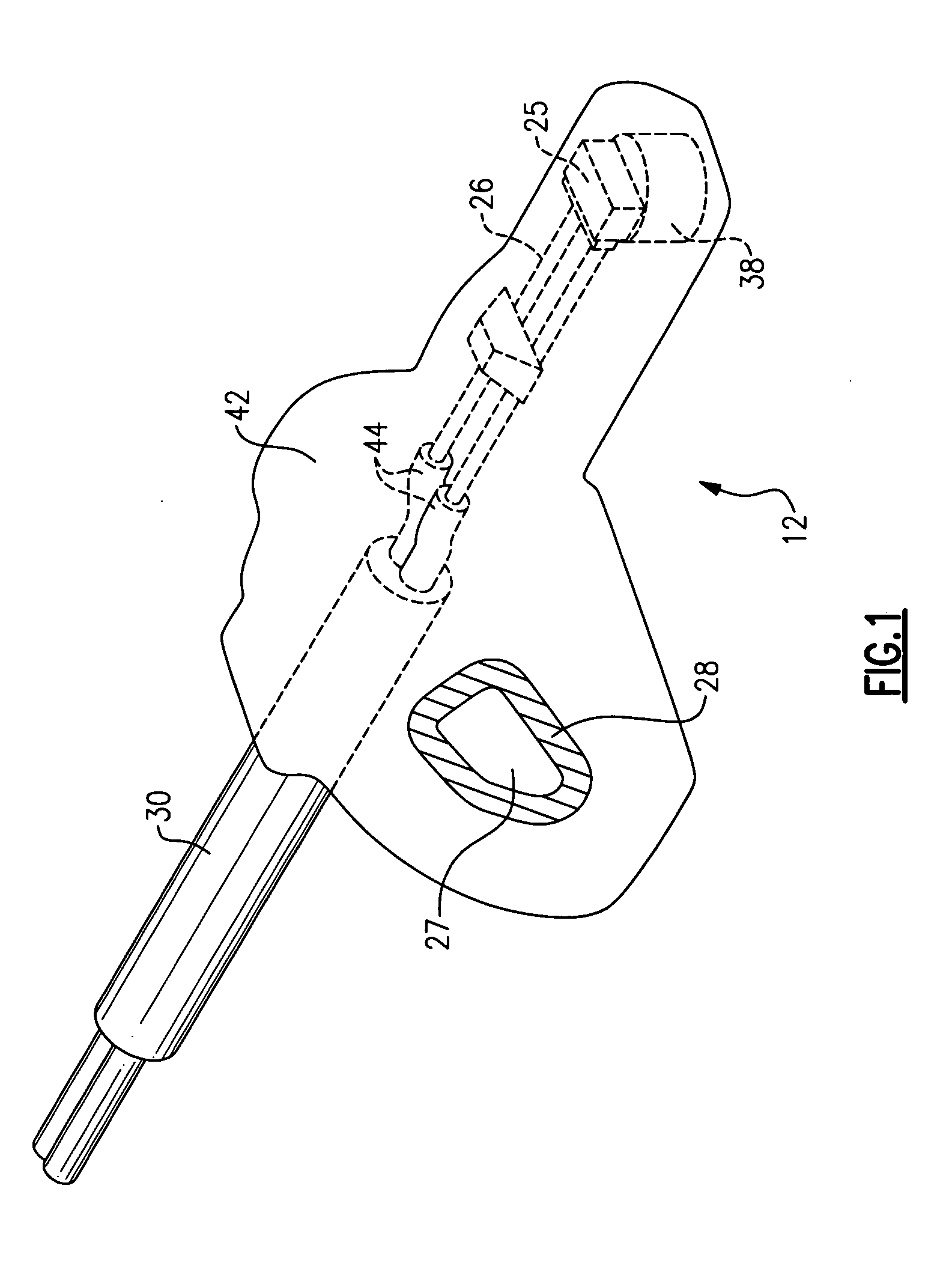
[0015] Referring to FIG. 1, a sensor assembly 12 includes a Hall-effect sensor 26 that is encapsulated within a plastic overmold 42. The Hall-effect sensor 26 is connected to leads 44 disposed within a cable sheath 30. The cable sheath 30 is partially encapsulated within the overmold 42 to prevent water intrusion. The speed sensor also includes an integrated circuit 25 connected to the Hall-effect sensor 26. The integrated circuit 25 extends over and adjacent a magnet 38 that is utilized for certain application specific requirements. The speed sensor includes an insert 28 that defines a mounting opening 27. As appreciated, the specific arrangement of the components within the speed sensor may be different than that illustrated to accommodate application specific requirements.

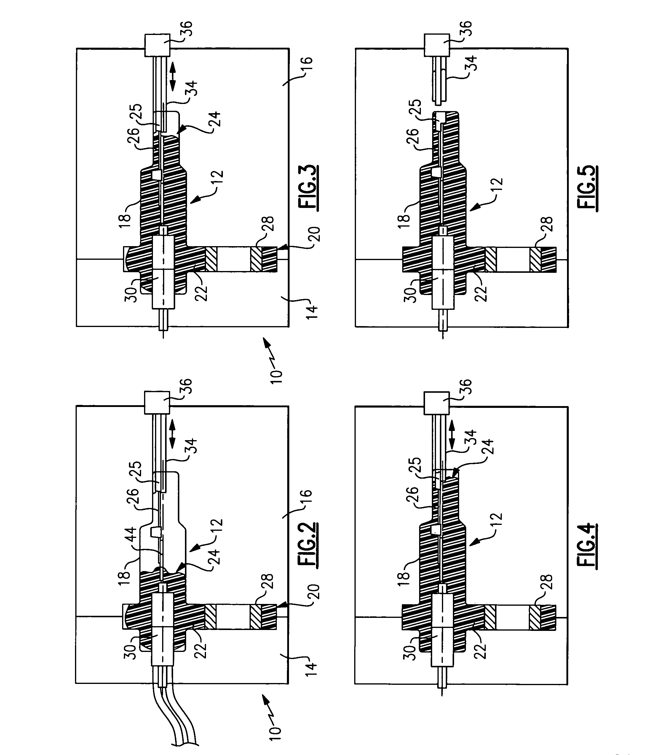
[0016] During operation, the speed sensor assembly 12 is typically exposed to moisture and other contaminants that can intrude into the encapsulated material and potential damage sensor components. Any passage ...


PUM


Abstract

A sensor assembly includes a Hall-effect sensor and an integrated circuit that are encapsulated with an encapsulating material. The Hall-effect sensor and integrated circuit are held in place during filling of the cavity by a retractable slide. Once the cavity is filled such that the encapsulating material can support the internal components in a desired position, the retractable slide is removed from the cavity. The encapsulating materials fill any voids created by the retractable slide to prevent the formation of additional openings within the completed encapsulated sensor assembly

Description

BACKGROUND OF THE INVENTION [0001] This invention generally relates to a method of building a speed sensor assembly. More particularly, this invention relates to a method of overmolding a speed sensor assembly to minimize vulnerability to water intrusion. [0002] A speed sensor is utilized to monitor the speed of a rotating element, such as a wheel or shaft. Speed sensors are necessarily mounted proximate the rotating element. In many applications, such as for monitoring wheel speed, the environment is particularly harsh for sensor components. Accordingly, conventional speed sensors are overmolded with plastic to protect the delicate circuits and sensor components from water and other debris. [0003] Overmolding of the sensor assembly is accomplished by supporting the circuit and other components within a mold cavity by one or more support pins. The pins extend into the mold and into contact with the internal components of the sensor to hold those components firmly during the injectio...

Claims


Application Information

Patent Timeline
IPC IPC(8): B29C45/14
CPCB29C45/14073B29K2105/24G01D11/245G01P1/026B29K2105/246
Inventor BIERSLAKER, JOHN E.LE-BIAN, MICHAEL
Owner SIEMENS VDO AUTOMOTIVE CORP
Why Eureka
Try Eureka