Control method, control system, RFID antenna and connection investigation method

a control method and antenna technology, applied in the field of system using rfid technique, can solve the problems of entanglement of cost and time for changing the procedure for using the rfid antenna, and ineffective use of the rfid antenna, so as to reduce the cost and time for changing the use procedur

Inactive Publication Date: 2007-08-16
HITACHI LTD
View PDF10 Cites 34 Cited by
  • Summary
  • Abstract
  • Description
  • Claims
  • Application Information

AI Technical Summary

Benefits of technology

[0013] According to the present invention, it is possible to operate even adjacent RFID antennas when they do not cause interference. Thus, RFID antennas can be used effectively. Further, it is possible to detect a combination of RFID antennas that causes interference when they are used simultaneously, to change a use procedure of RFID antennas. As a result, even when unexpected combination of RFI

Problems solved by technology

As a result, the technique described in the patent document 2005-157645 does not use the RFID antennas effectively.
Thus, it is possible that the technique described in 2005-15764 c

Method used


Image

  • Control method, control system, RFID antenna and connection investigation method
  • Control method, control system, RFID antenna and connection investigation method
  • Control method, control system, RFID antenna and connection investigation method

Examples


Embodiment Construction

[0029] Now, one embodiment of the present invention will be described in detail referring to the drawings.

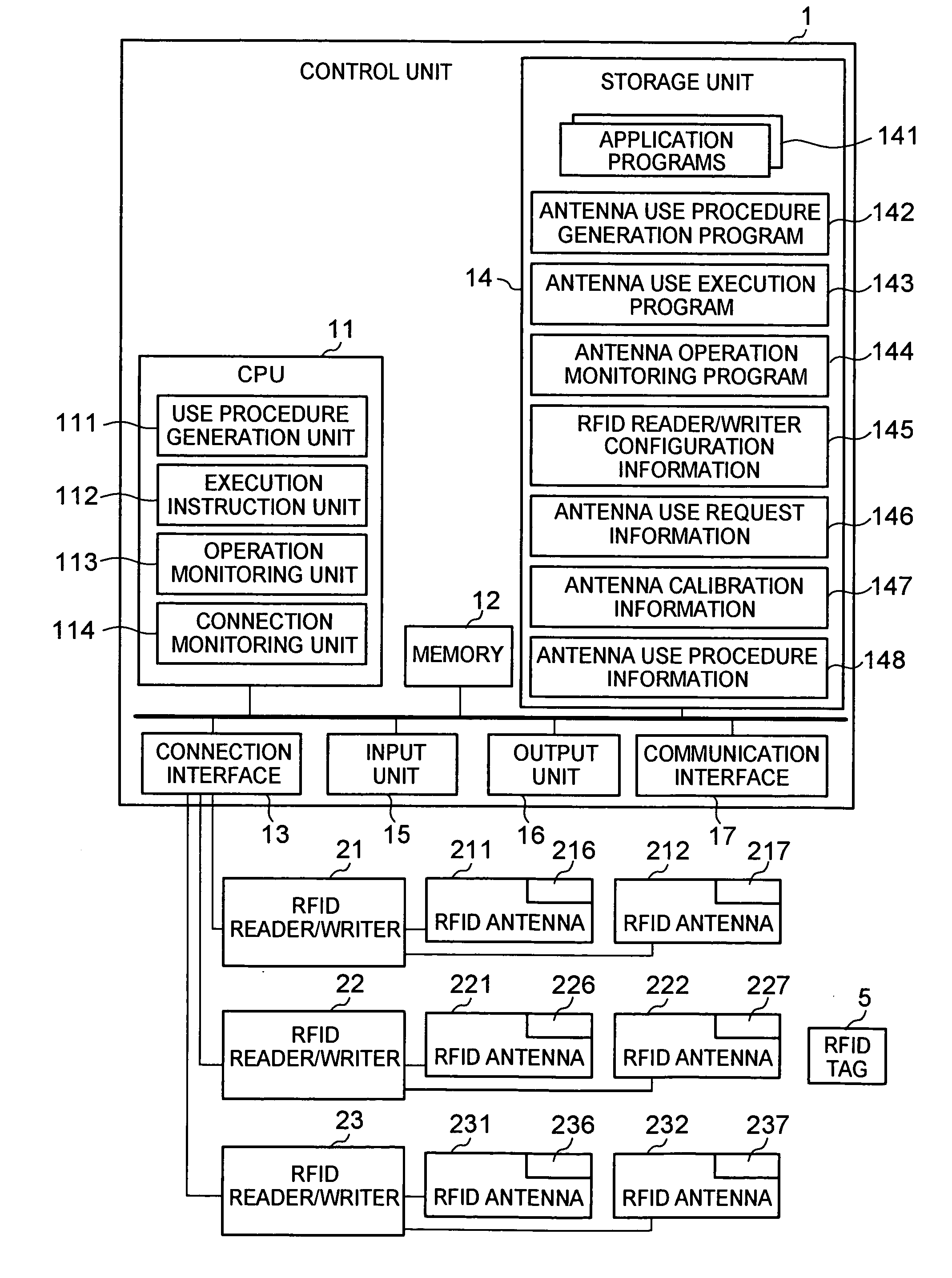
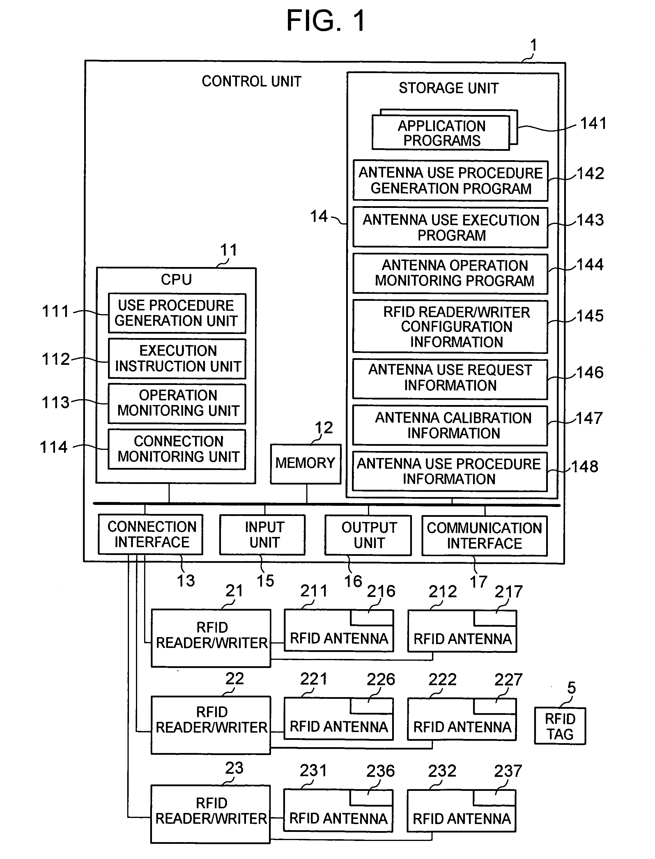
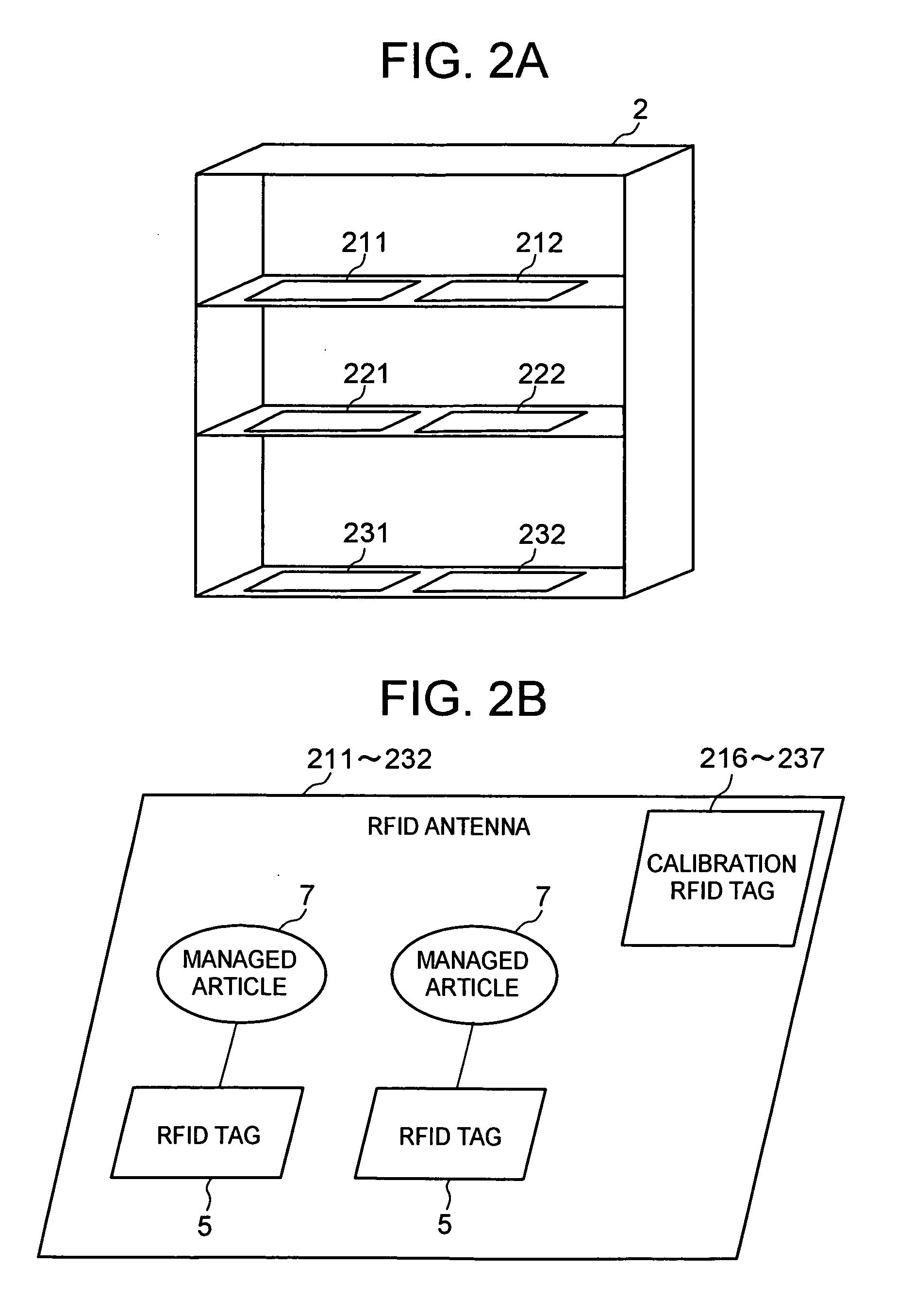
[0030]FIG. 1 is a diagram showing an example of a configuration of the present embodiment. As shown in FIG. 1, a system of the present embodiment comprises: a control unit 1; RFID reader / writers 21-23; RFID antennas 211, 212, 221, 222, 231 and 232; and an RFID tag 5. The RFID antennas 211, 212, 221, 222, 231 and 232 have respective calibration RFID tags 216-237.

[0031] The control unit 1 is connected with the RFID reader / writers 21, 22 and 23. The RFID reader / writer 21 is connected with the RFID antennas 211 and 212, the RFID reader / writer 22 with the RFID antennas 221 and 222, and the RFID reader / writer 23 with the RFID antennas 231 and 232.

[0032] The control unit 1 acquires a combination of RFID antennas 211-232 that can not be activated at the same time, based on results of write and read to and from the calibration tags 216-237 of the RFID antennas 211-232 themselves. Then...


PUM


Abstract

A technique of preventing occurrence of interference even when a plurality of RFID antennas are used simultaneously. Each RFID antenna is attached with a calibration RFID tag. A combination of RFID antennas that causes a problem is acquired based on whether information held by the calibration RFID tag can be read from each of the RFID antennas that have performed reading simultaneously. Then, an RFID antenna use procedure is generated such that the RFID antennas in the acquired combination are not used simultaneously. Each RFID antenna is operated according to the generated use procedure.

Description

BACKGROUND OF THE INVENTION [0001] 1. Field of the Invention [0002] The present invention relates to a system using the RFID technique. [0003] 2. Description of the Prior Art [0004] To access an RFID tag in the RFID (Radio Frequency Identification) technique, an RFID reader / writer transmits a carrier wave to the RFID tag through an RFID antenna connected to the RFID reader / writer. Receiving a carrier wave, the RFID tag reads data held in it and returns the data, for example. Or, receiving a carrier wave, the RFID tag writes data. [0005] Sometimes, a plurality of RFID antennas are used in order to widen the read range for an RFID tag. In that case, an RFID antenna changer is introduced between an RFID reader / writer and RFID antennas. An RFID antenna changer connects one RFID reader / writer and a plurality of RFID antennas, and changes an antenna connected to the RFID reader / writer so that one antenna is activated among the plurality of antennas. Thus, one RFID reader / writer performs w...

Claims


Application Information

Patent Timeline
IPC IPC(8): G08B13/14G01N37/00G01R35/00
CPCG06K7/0008G06K17/00G06K7/10356
Inventor MOCHIZUKI, TOMOYUKISANO, HIDEKI
Owner HITACHI LTD
Why Eureka
Try Eureka