
Touch detection

a technology of touch detection and detection system, applied in the direction of instruments, electric digital data processing, input/output process of data processing, etc., can solve the problems of increased cost of producing large screens, increased time requirements, and detrimental effect on productivity, and achieve the effect of increasing the touch resolution

Active Publication Date: 2007-08-16
TPK HLDG
View PDF7 Cites 34 Cited by
  • Summary
  • Abstract
  • Description
  • Claims
  • Application Information

AI Technical Summary

Benefits of technology

[0032]Other objects and advantages of the present invention will become obvious to the reader and it is intended that these objects and advantages are within the scope of the present invention.

Problems solved by technology

Reflections from the substrate boundaries cause detection problems therefore certain materials that reduce s these reflections are required on the edges of the screen.
This requires additional time during manufacturing, and has a detrimental effect on productivity.
Secondly, more memory is necessary, resulting in increased cost for producing larger screens.
The issue with this approach is the reflections from boundaries of the substrate and the manufacturing cost as a result of that.

Method used


Image

  • Touch detection
  • Touch detection
  • Touch detection

Examples


Embodiment Construction

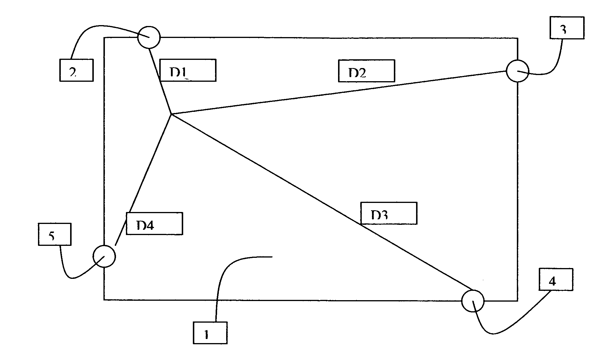
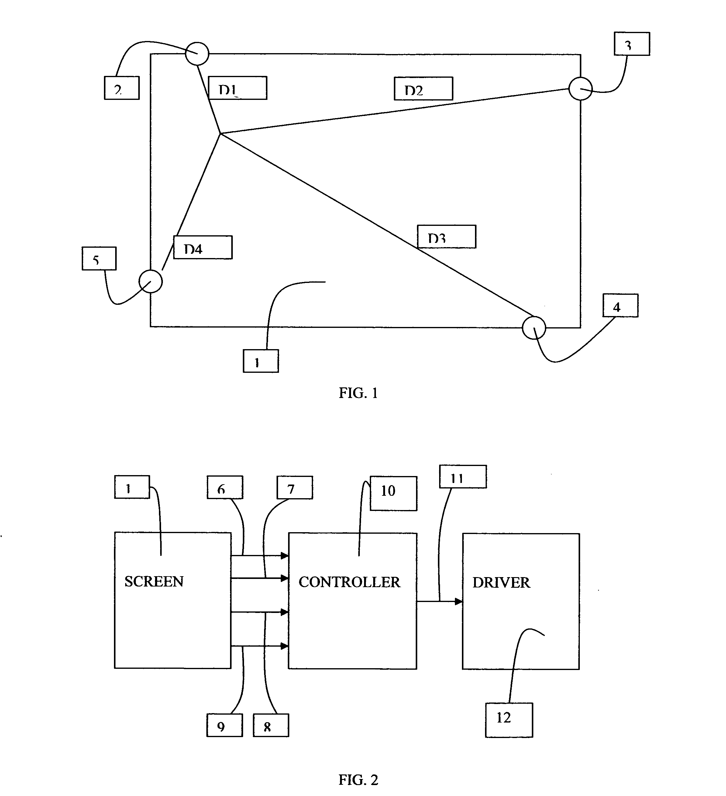
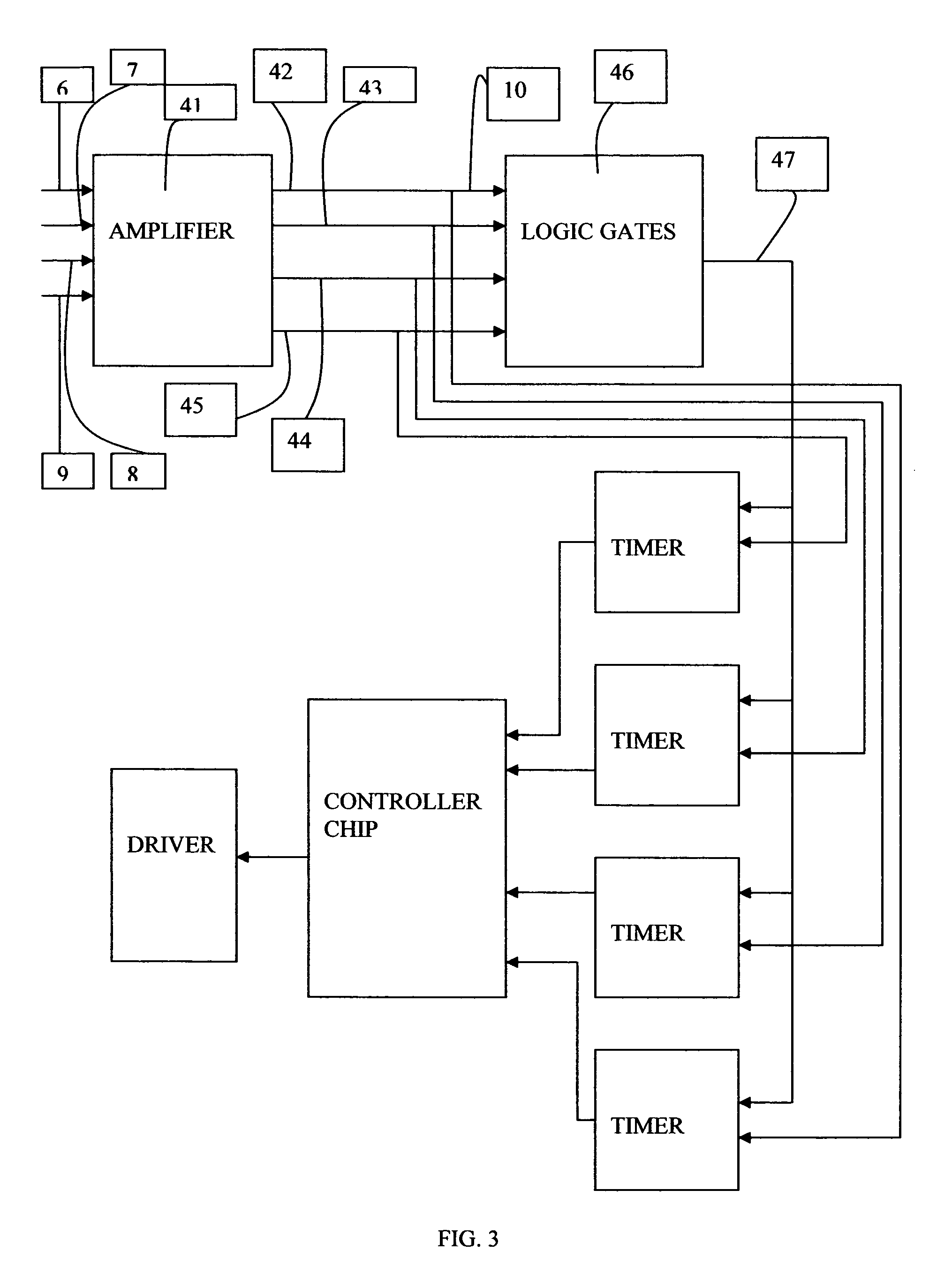
[0041]Turning now descriptively to the drawings, in which similar reference characters denote similar elements throughout the several views, the attached figures illustrate a touch detection, which comprises a surface 1 where a touch on the surface generates acoustic waves, transducers 2, 3, 4, 5 that detect these waves, a controller 10 that calculates the location of the touch and a host device where the touch position is used to communicate with an application program. The screen 1 is formed from any material that is capable of propagating bending waves. Four transducers 2, 3, 4, 5 are placed on the screen 1. These transducers 2, 3, 4, 5 detect bending waves generated on the screen 1. The output of each transducer 2, 3, 4, 5 is sent to the controller unit 10. Controller unit 10 has an amplifier unit 41, a logic gates unit 46, timers 13, 14, 15, 16 and microcontroller 21. Signals coming from the screen 1 are applied to these timers to detect the time differences to be used in deter...


PUM


Abstract

A touch detection device for detecting touches on a given surface. The inventive device includes a surface where a touch generates acoustic waves, transducers that detect these waves, a controller that calculate the location of the touch and a host device where the touch position is used to communicate with the application program. The screen is formed from any material that is capable of propagating acoustic waves. Plurality transducers are placed on the screen. These transducers detect acoustic waves generated on the screen. The screen is calibrated by touching it once and a map of arrival time ratios are generated and saved in the storage unit. During the real time operation, a touch on the screen generates acoustic waves that are detected by transducers. The output of each transducer is sent to a controller unit where the time differences and their ratios are calculated and compared to time ratios in the storage unit to detect the touch location.

Description

BACKGROUND OF THE INVENTION[0001]1. Field of the Invention[0002]This application claims the benefit of U.S. Provisional Application No. 60 / 771,681. The present invention relates generally to touch detection and more specifically it relates to a touch detection system for detecting touches on a given surface.[0003]2. Description of the Related Art[0004]Touch detection has been in use for years. Typically, touch detection is comprised of products that determine the location of a touch based on resistive, capacitive, infrared, surface acoustic waves, force and bending waves. Those devices that utilize acoustic waves to determine the touch location are based on either by measuring the time of flight or by measuring the phase differences and / or characterizing the screen.[0005]U.S. Pat. No. 6,922,642 teaches how to generate acoustic waves on a surface that is capable of transmitting acoustic waves. Furthermore, this patent teaches how to generate dispersion corrected convolution function,...

Claims


Application Information

Patent Timeline
Patent Type & Authority Applications(United States)
IPC IPC(8): G06F3/043
CPCG06F3/0433G06F3/0436
Inventor BAYRAMOGLU, GOKALPBAYRAMOGLU, NIHAT DENIZ
Owner TPK HLDG
Learn More