A liquid crystal array type infrared touch screen

An infrared touch screen, liquid crystal array technology, applied in optics, instruments, electrical digital data processing, etc., can solve problems such as overall sensitivity decline and light intensity decline, and achieve touch screen sensitivity assurance, high arrangement density, and improved touch resolution. Effect

Active Publication Date: 2017-09-15
NANJING INST OF ADVANCED LASER TECH
View PDF4 Cites 0 Cited by
  • Summary
  • Abstract
  • Description
  • Claims
  • Application Information

AI Technical Summary

Problems solved by technology

[0004] But there is following defective in above-mentioned technical scheme: because infrared emitting diode is bundled by light-transmitting reflector group, the infrared light of each beam is very weak, for example uses one hundred light-transmitting reflectors, so each light-transmitting reflector has only one hundred on average. One-third of the light intensity of the infrared emitting diode, if the number of light-transmitting mirrors is increased in order to improve the resolution, the light intensity will also decrease. Overall Sensitivity Decrease

Method used


Image

  • A liquid crystal array type infrared touch screen
  • A liquid crystal array type infrared touch screen
  • A liquid crystal array type infrared touch screen

Examples


Embodiment 1

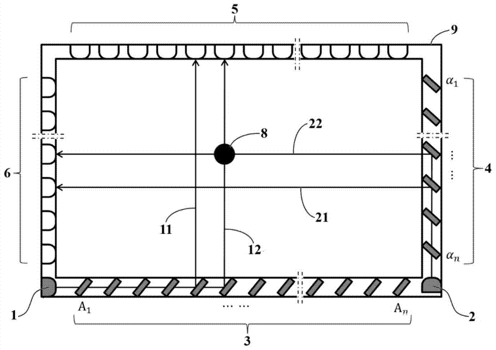
[0033] This embodiment is the implementation of the first technical solution of the present invention. Such as image 3 As shown, a row of cholesteric liquid crystal arrays 3 and 4 are respectively arranged on one long side and a short side of the touch screen 9, and a row of infrared liquid crystal arrays are arranged on the other long side and short side of the touch screen 9. Detector arrays 5 and 6, infrared detectors correspond to the cholesteric liquid crystal reflection light path on the opposite side; the pitch of the cholesteric liquid crystals in the cholesteric liquid crystal arrays 3 and 4 is the same, so that all the cholesteric liquid crystals in one array have the same pitch. The helical structure of liquid crystals is the same.

[0034] The working mode of the device described in this embodiment is as follows:

[0035] The scanning voltage control device (not shown in the figure) gives image 3 Cholesteric liquid crystal A in the cholesteric liquid crystal a...

Embodiment 2

[0039] In order to improve the response speed, on the basis of Embodiment 1, infrared emitting tubes 1 are respectively provided at both ends of the long sides. Such as Figure 4 As shown, the cholesteric liquid crystal array 3 is divided into two sections, and the first section includes the cholesteric liquid crystal A 1 to A n , the second segment includes cholesteric liquid crystal B 1 to B n , the light emitted by the infrared emission tube 1 at the left end is emitted by the cholesteric liquid crystal A 1 to A n Reflection, the light emitted by the infrared emission tube 1 at the right end is emitted by the cholesteric liquid crystal B 1 to B n Reflection; in the short side, the light emitted by the infrared emitting tube 2 is controlled by the cholesteric liquid crystal α in the cholesteric liquid crystal array 4 1 to α n reflection. Cholesteric liquid crystal A 1 to A n , B 1 to B n 、α 1 to α n The three-segment array scans at the same time, so the longes...

Embodiment 3

[0041] Such as Figure 5 As shown, on the basis of embodiment 2, an infrared emission tube 1 and reflector 7 are added in the middle of the long side, and the infrared rays emitted vertically by the infrared emission tube 1 are reflected to the long side direction through the reflector 7; Infrared emission tubes 2 are arranged at both ends of the side, the cholesteric liquid crystal array 3 is divided into three sections, the cholesteric liquid crystal array 4 is divided into two sections, and the cholesteric liquid crystal A 1 to A n Reflecting the light from infrared emission tube 1 at the left end, cholesteric liquid crystal B 1 to B n Reflecting the light from the infrared emission tube 1 in the middle of the long side, cholesteric liquid crystal C 1 to C n Reflecting the light from infrared emission tube 1 at the right end, cholesteric liquid crystal α 1 to α n Reflect the light from the upper infrared emission tube 2, cholesteric liquid crystal β 1 to beta n Refl...


PUM


Abstract

The invention relates to a liquid crystal array infrared touch screen. The liquid crystal array infrared touch screen comprises a touch screen outer frame (9), a plurality of infrared light-emitting diodes (1 and 2), two cholest-type liquid crystal arrays (3 and 4), two infrared detector arrays (5 and 6) and a scanning voltage control device. According to the technical scheme, the cholest-type liquid crystal arrays are used for substituting a semi-transparent semi-reflecting mirror in the prior art, the scanning voltage control device applies a voltage to each liquid crystal in the liquid crystal arrays, cholest-type liquid crystals are sequentially controlled to be switched between a transmission state H and a reflection state P, so that the infrared ray emitted by the infrared light-emitting diodes respectively scans along a long side edge and a short side edge, the emission light intensity can be maintained since the infrared ray is not split, and the sensitivity of the touch screen under the same power consumption can be guaranteed; under the situation of not being subjected to the restriction of the beam splitting light intensity, the quantity of scanning rays in a unit length can be increased, and the touch resolution can be further improved; meanwhile, an individual cholest-type liquid crystal panel used for reflection and transmission can be minimized, so that the arrangement density can be higher, and the touch resolution can be improved.

Description

technical field [0001] The invention relates to the field of photoelectric touch screens, in particular to a liquid crystal array type infrared touch screen. Background technique [0002] Touch screen, also known as touch screen and touch panel, is an inductive display device that can receive input signals such as contacts. When touching the graphic buttons on the screen, the tactile feedback system on the screen can It can drive various connection devices and can be used to replace the mechanical button panel. Infrared detection is a commonly used touch screen implementation method. Infrared detection technology can simply realize the infrared detection method by using the same wavelength infrared emitting tube and infrared receiving tube (referred to as infrared pair tube), as long as there is an object blocking the infrared pair tube. If the connection is not connected, the received signal will drop sharply, so infrared rays can detect the blocking of objects, and are wi...

Claims


Application Information

Patent Timeline
Patent Type & Authority Patents(China)
IPC IPC(8): G06F3/042G02F1/1333
CPCG02F1/13338G06F3/0421
Inventor 王欢田尚陈昱
Owner NANJING INST OF ADVANCED LASER TECH
Why Eureka
Try Eureka