Optical substrate for enhanced detectability of fluorescence

a technology of optical substrates and fluorescence, applied in the field of sample substrates, can solve the problems of reducing reflectance and being unable to define the location of reflection surfaces, and achieve the effect of increasing sample excitation and fluorescence emission

Inactive Publication Date: 2007-08-16
OERLIKON TRADING AG TRUEBBACH
View PDF19 Cites 74 Cited by
  • Summary
  • Abstract
  • Description
  • Claims
  • Application Information

AI Technical Summary

Benefits of technology

[0018] It is therefore an object of the present invention to provide an improved sample substrate which provides increased sample excitation and fluorescence emission without the disadvantage to base the reflection of the excitation wavelength completely on the reflectivity of a metal surface. It is another important aspect of the present invention to disclose a sample substrate providing maximum enhancement of the fluorescence signal for two or more different excitation wavelengths. It is yet another aspect of the present invention to disclose a sample substrate providing application adjusted enhancement factors for two or more excitiation wavelengths.

Problems solved by technology

An additional layer added on top of the interference reflector can cause a decrease in reflectance.
In addition for such an interference reflector it is not possible to define the location of a reflection surface since most of coating layers contribute to the reflection.

Method used


Image

  • Optical substrate for enhanced detectability of fluorescence
  • Optical substrate for enhanced detectability of fluorescence
  • Optical substrate for enhanced detectability of fluorescence

Examples


Embodiment Construction

[0028] The sample substrate of the present invention can be used in any of a wide number of possible fluorescence microscope systems, including, for example, those described in U.S. Pat. No. 4,284,897 to Sawamura et al., U.S. Pat. No. 5,091,652 to Mathies et al., U.S. Pat. No. 5,296,700 to Kumagai, U.S. Pat. No. 5,381,224 to Dixon et al., and U.S. Pat. No. 5,504,336 to Noguchi, as well as U.S. patent application Ser. Nos. 08 / 595,355, 08 / 616,174 and 08 / 791,684.

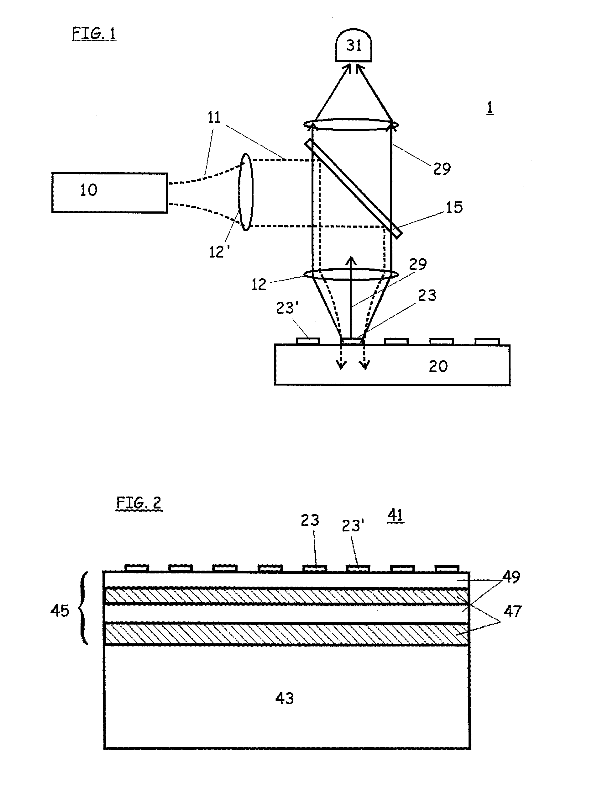
[0029] A preferred fluorescence imaging system 1 for use with the present invention is illustrated in FIG. 1: A light source 10, for example a laser, produces an stimulating beam 11. The stimulating beam 11 is preferably a collimated beam of monochromatic coherent light. However, a noncoherent source, such as a light emitting diode (LED) could be used and a noncollimated source could be coupled to collimating optics to create a collimated beam. If the stimulating beam 11 is not monochromatic, it may be directed through a filte...


PUM

PropertyMeasurementUnit
wavelength rangeaaaaaaaaaa
reflectivityaaaaaaaaaa

Abstract

A sample substrate adapted for use with fluorescence excitation light with a first wavelength. A reflector is disposed on a base. The reflector includes a reflecting multilayer interference coating with at least two layers. Not all of the layers L fulfill a quarterwave condition: dL·nL=(2N+1)·¼ wherein dL is a physical thickness of layer L, nL is an index of refraction of layer L at the first wavelength, N is an integer equal to or greater than zero and 1 is the first wavelength. Thicknesses of the layers ensure that any fluorescent sample material disposed on top of said multilayer interference coating would be located near an antinode of a standing wave formed by the excitation light with the first wavelength incident on said substrate.

Description

BACKGROUND OF THE INVENTION [0001] The present invention relates to sample substrates, such as plates, slides and cells, for use in examining, indicating, analyzing or identifying fluorescent, phosphorescent or luminescent sample materials, e.g. tagged molecular biological specimens, and in particular relates to such sample holders whose optical structures are adapted for enhancing fluorescence detection and imaging. The format of the sample substrates of the present invention can be adapted to formats typically used in this field, such as for example the standard format of microtiter plates. [0002] Fluorescence microscopy is often used in the fields of molecular biology, biochemistry and other life sciences for analyzing biological molecules, including nucleic acids (DNA, RNA) and proteins (enzymes, antigens, etc.) that have been tagged or labeled with fluorescent probes. One such use is DNA diagnostics, such as for gene detection, in which a DNA sample is deposited on and bound to...

Claims


Application Information

Patent Timeline
Patent Type & Authority Applications(United States)
IPC IPC(8): G01N21/01G01N21/64G02B5/28
CPCG01N21/0303G02B5/285G01N21/6452
Inventor KRAUS, JORGEDLINGER, JOHANNESWIKI, MAXTHOME-FORSTER, HEIDIHEINE-KEMPKENS, CLAUSMAISENHOELDER, BERNDKASPAR, MARTIN
Owner OERLIKON TRADING AG TRUEBBACH
Why Eureka
Try Eureka