Electrical switching apparatus and receptacle including automatic miswiring protection
a technology of electrical switching apparatus and receptacle, applied in the field of receptacles, to achieve the effect of preventing downstream power flow
- Summary
- Abstract
- Description
- Claims
- Application Information
AI Technical Summary
Benefits of technology
Problems solved by technology
Method used
Image

Examples
example 1
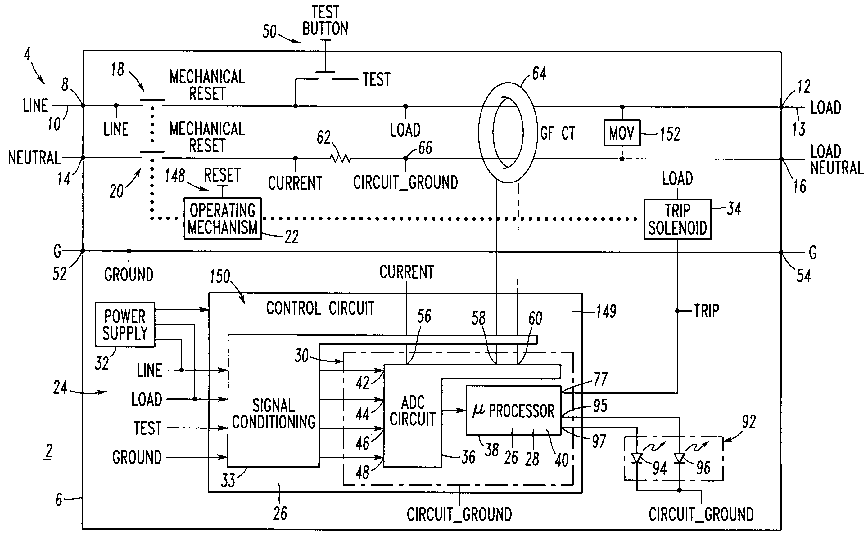
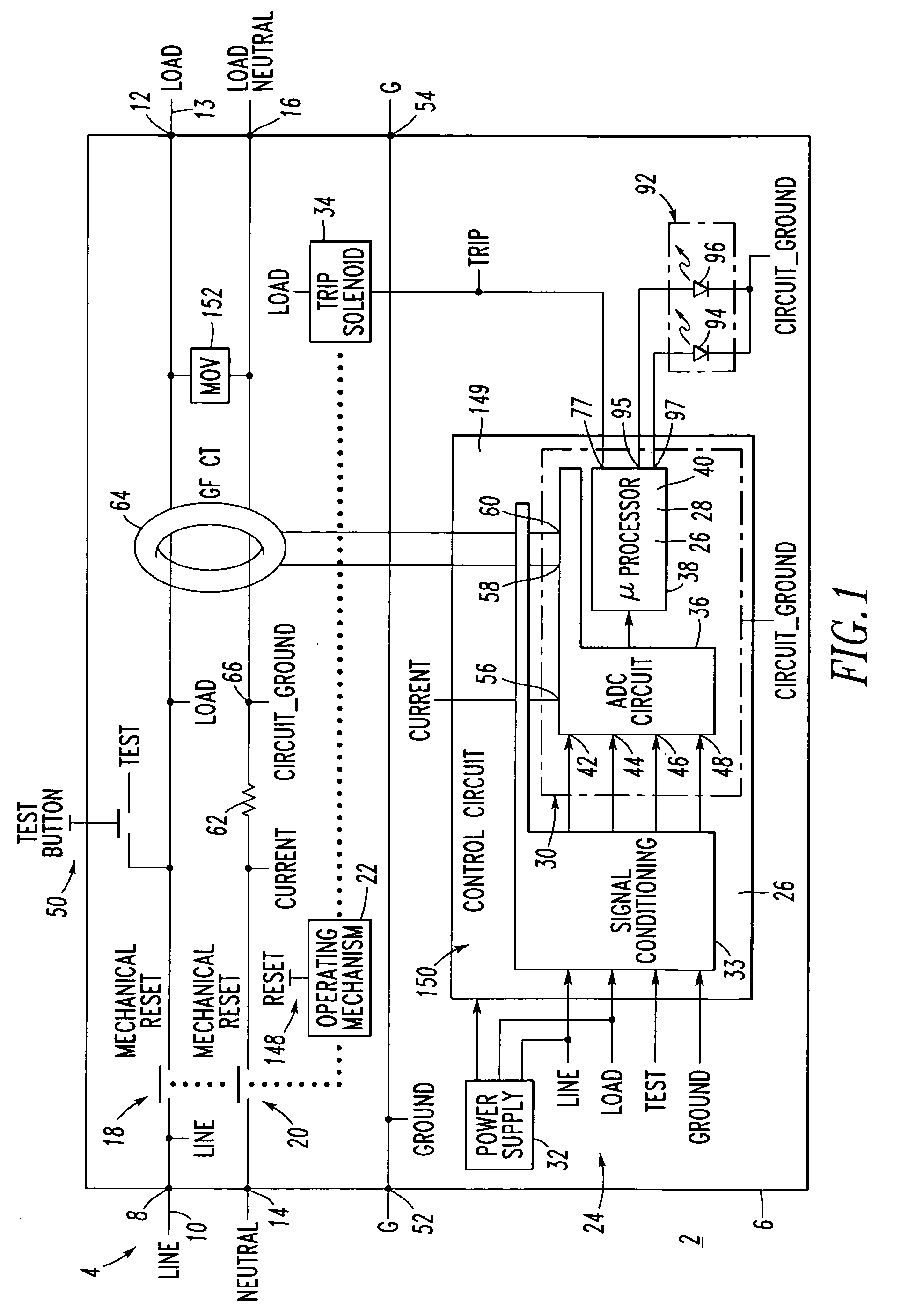
[0039] The example trip mechanism 24 includes a microcontroller 30, a power supply 32, a signal conditioning circuit 33 and a trip solenoid 34. The microcontroller 30 includes the ADC circuit 36 and a microprocessor 38 having a firmware routine 40. The ADC circuit 36 includes a plurality of sensors, such as ADC inputs 42, 44, 46, 48 for sensing voltages respectively corresponding to the line terminal 8 (LINE), the load terminal 12 (LOAD), a test button 50 (TEST) and one or more ground terminals 52, 54 (GROUND). The ADC circuit 36 further includes a plurality of sensors, such as ADC inputs 56 and 58, 60, for sensing voltages corresponding to a neutral shunt 62 (CURRENT) and the two sense inputs from a ground fault current transformer 64, respectively. The microcontroller 30 and the various voltages are referenced to a circuit ground (CIRCUIT_GROUND) on the load neutral side of the neutral shunt 62 at node 66.
[0040] The neutral shunt 62 includes a voltage (CURRENT) corresponding to c...
example 2
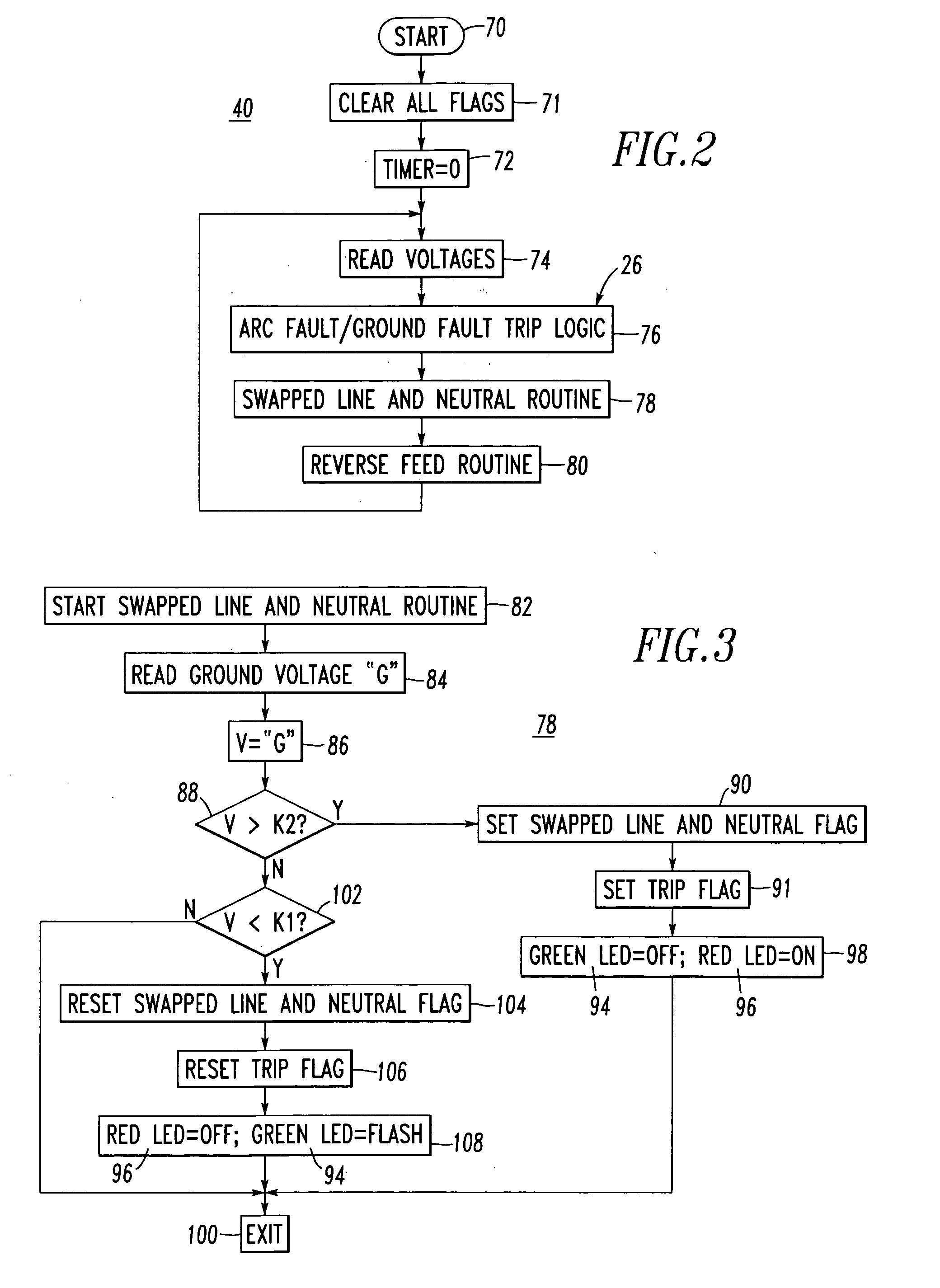
[0042] Referring to FIG. 2, the example firmware routine 40 is shown. After starting at 70, all subsequently employed flags are cleared, at 71, and a timer (e.g., hardware; firmware) value is set to zero at 72. Next, at 74, the microprocessor 38 (FIG. 1) reads and suitably processes the various voltages corresponding to the ADC inputs 42,44,46,48,56,58,60. Then, at 76, arc fault / ground fault trip logic is executed to process the current value associated with the ADC input 56 and the two sense inputs from the ground fault current transformer64 at ADC inputs 58,60. Under arc fault or ground fault trip conditions, the microprocessor 38 sets a digital output 77, which provides a TRIP signal to the trip solenoid 34, in order to trip open the separable contacts 18,20. Next, at 78, a swapped line and neutral routine (FIG. 3) is executed after which, at 80, a reverse feed routine (FIG. 4) is executed, after which step 74 is repeated.
[0043] The microprocessor 38 and the firmware routine ste...
example 3
[0044] Referring to FIG. 3, the swapped line and neutral routine 78 starts at 82. Next, at 84, the voltage of the ground terminal 52 (GROUND or “G”) with respect to the reference node 66 (CIRCUIT_GROUND) of FIG. 1 is read. Then, at 86, value V is set equal to the voltage “G”. Next, at 88, it is determined if value V is greater than a predetermined value K2 (e.g., without limitation, a suitable value; about 60 VAC). If so, then at 90, a swapped line and neutral flag is set and, at 91, a trip flag is set. As will be discussed, below, in connection with FIG. 4, responsive to the trip flag, the microprocessor 38 (FIG. 1) sets the digital output 77, which provides the TRIP signal to the trip solenoid 34, in order to trip open the separable contacts 18,20.
[0045] For purposes of indication, the receptacle 2 preferably includes a suitable indication circuit 92 (FIG. 1) structured to indicate different fault conditions. For example, the circuit 92 includes a first LED 94 driven by microproc...
PUM
 Abstract
Description
Claims
Application Information
 - Generate Ideas
- Intellectual Property
- Life Sciences
- Materials
- Tech Scout
- Unparalleled Data Quality
- Higher Quality Content
- 60% Fewer Hallucinations
Browse by: Latest US Patents, China's latest patents, Technical Efficacy Thesaurus, Application Domain, Technology Topic, Popular Technical Reports.
© 2025 PatSnap. All rights reserved.Legal|Privacy policy|Modern Slavery Act Transparency Statement|Sitemap|About US| Contact US: help@patsnap.com