Light guide plate

a technology of light guide plate and guide plate, which is applied in the direction of instruments, lighting and heating apparatus, optical elements, etc., can solve the problems of reducing yield, interference fringes, or moire interference, and reducing the brightness of the light emitting surface, so as to achieve uniform light intensity and increase yield

Inactive Publication Date: 2007-08-16
CITIZEN ELECTRONICS CO LTD
View PDF7 Cites 48 Cited by
  • Summary
  • Abstract
  • Description
  • Claims
  • Application Information

AI Technical Summary

Benefits of technology

[0025]In the light guide plate, even if the depth of the grooves is made small, the apex angle of the prism can be adjusted appropriately by varying the width of the groove. Accordingly, the intensity of light emitted from the light emitting surface can be made uniform across the entire light emitting surface, and hence the brightness on the light emitting surface can be made uniform. In addition, because the depth of the groove can be made small, the resin material is allowed to flow smoothly in injection molding process of the light guide plate. Thus, the yield can be increased. In addition, one mold segment can be recycled a plurality of times. Further, because the widths of the grooves are adjustably varied, interference fringes are unlikely to occur on the liquid crystal display panel.

Problems solved by technology

Consequently, the flowability of the molding material degrades, which leads to a reduction in yield.
In addition, the prisms of the conventional light guide plate have a constant pitch and therefore are likely to produce interference fringes, or moire interference, on the associated liquid crystal display panel.
A great deal of cost and time are therefore required for the reformation of the plating layer 82.

Method used


Image

  • Light guide plate
  • Light guide plate
  • Light guide plate

Examples


Embodiment Construction

[0040]An embodiment of the present invention will be described below in detail with reference to the accompanying drawings.

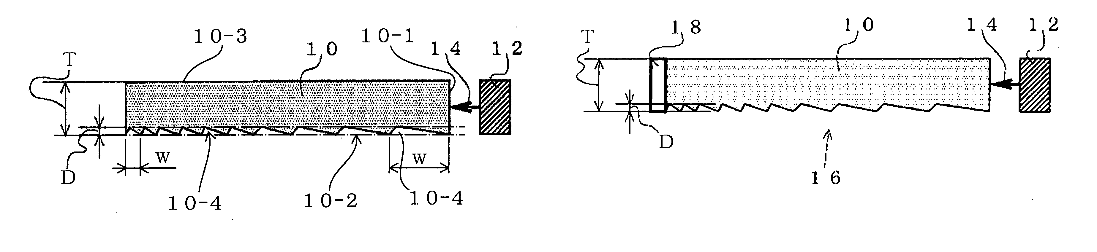
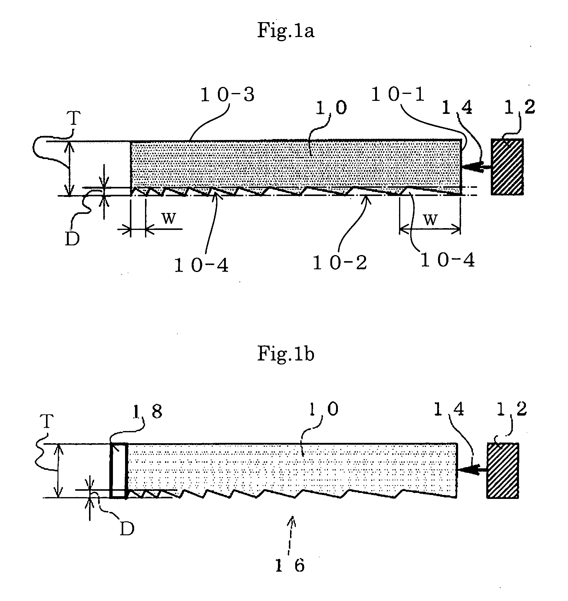
[0041]FIG. 1a shows a light guide plate 10 according to an embodiment of the present invention. The light guide plate 10 is rectangular in a plan view and has a rectangular peripheral surface including a light receiving plane surface 10-1 for receiving light from a LED light source 12, a reflecting or prism surface (lower side surface in FIG. 1a) 10-2 and a light emitting surface (upper side surface in FIG. 1a) 10-3. The light received into the light guide plate 10 through the light receiving plane surface 10-1 is emitted through the light emitting surface 10-3 by the action of the reflecting surface 10-2. The reflecting surface comprises a plurality of grooves 10-4 extending parallel to the light receiving plane surface 10-1 of the light guide plate 10 to form prisms. Each of the grooves 10-4 has a cross-section in the shape of a triangle having a base flush wi...


PUM


Abstract

A light guide plate has a light emitting surface and a prism surface opposite to the light emitting surface. The prism surface includes a plurality of grooves extending parallel to each. The grooves have a constant depth, and widths of the grooves are varied, thereby adjusting the apex angles of the grooves. The depth of the grooves can be set to be not more than 20 microns.

Description

[0001]This application claims priority under 35 U.S.C. §119 to Japanese Patent Application No. JP2006-036684 filed Feb. 14, 2006, the entire content of which is hereby incorporated by reference.BACKGROUND OF THE INVENTION[0002]1. Field of the Invention[0003]The present invention relates to a light guide plate for use in a lighting device that illuminates a small-sized liquid crystal display mounted on a cellular phone, a personal digital assistant (PDA), etc.[0004]2. Description of the Related Art[0005]FIG. 3a illustrates a lighting device presently used to illuminate a small-sized liquid crystal display 58 of a cellular phone, a PDA, etc.[0006]The lighting device has a light source 12 using light-emitting diodes (hereinafter abbreviated as “LEDs”). A light guide plate 10 receives light from the light source 12 and emits the light upward while guiding it in the horizontal direction. A diffusing sheet 50 diffuses the light emitted from the light guide plate 10 and passes it upward. T...

Claims


Application Information

Patent Timeline
Patent Type & Authority Applications(United States)
IPC IPC(8): F21V7/04
CPCG02B6/0061G02B6/0038
Inventor WATANABE, KIYOKAZUMIYASHITA, JUNJI
Owner CITIZEN ELECTRONICS CO LTD
Why Eureka
Try Eureka