Improved volumetric cement mixer

Inactive Publication Date: 2007-08-16
CEMEN TECH
View PDF6 Cites 20 Cited by
  • Summary
  • Abstract
  • Description
  • Claims
  • Application Information

AI Technical Summary

Benefits of technology

[0013]The reinforced plastic has a lower coefficient of friction than steel or stainless steel conventionally used in cement mixers. Therefore, t

Problems solved by technology

Stainless steel bins are also known, though are much more costly than steel bins.
A major problem with steel bins is rusting, caused by the

Method used


Image

  • Improved volumetric cement mixer
  • Improved volumetric cement mixer
  • Improved volumetric cement mixer

Examples


Embodiment Construction

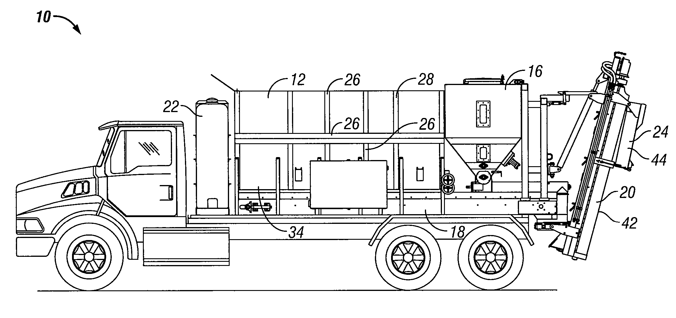
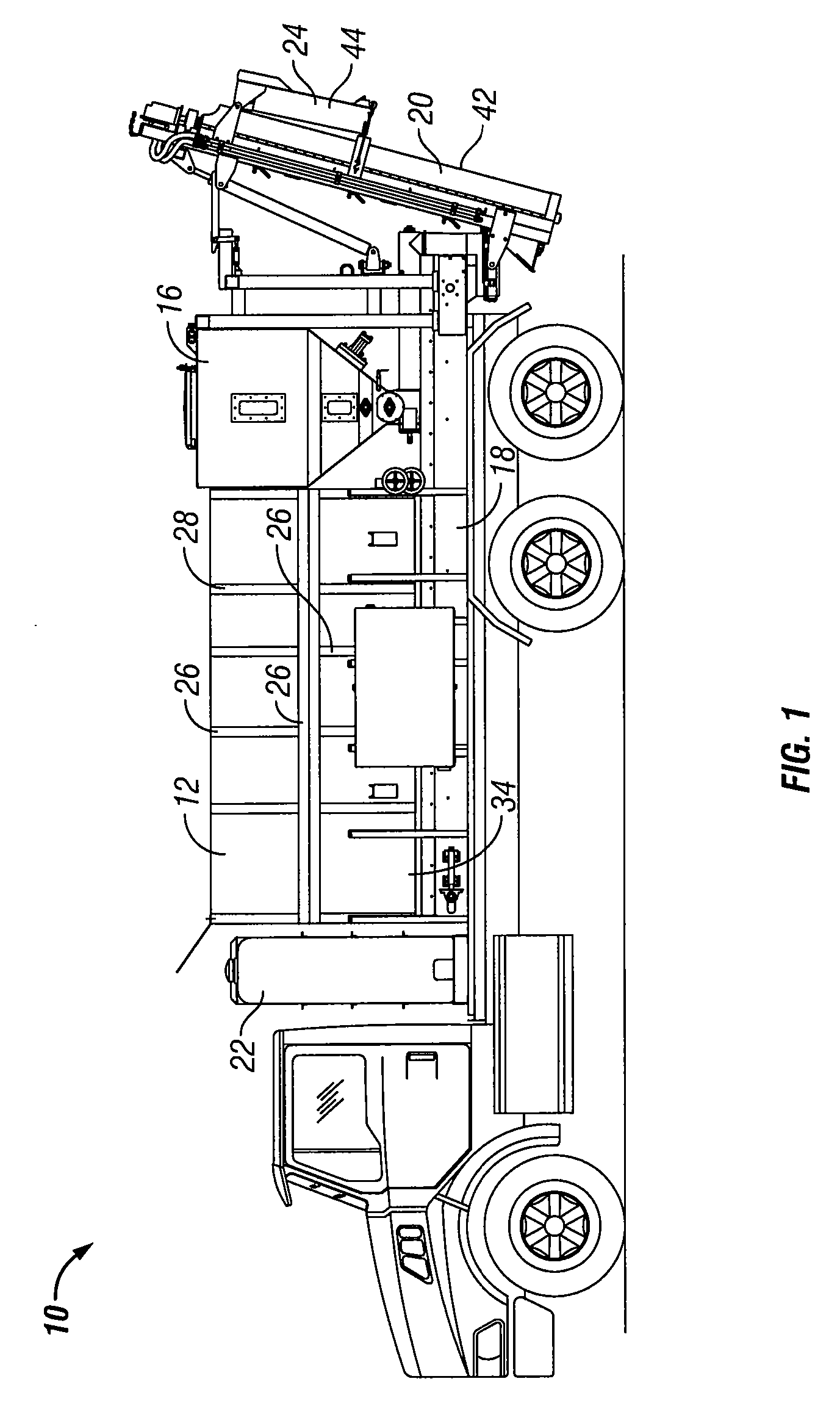
[0019]The volumetric cement mixer is generally designated in FIG. 1 by the reference numeral 10. The cement mixer 10 is shown to be mounted on a truck chassis so as to be portable. However, it is understood that the volumetric cement mixer of the present invention may also be built at or transported to a job site and set on the ground or other support structure so as to be non-portable.

[0020]The cement mixer 10 includes a pair of bins 12, 14 for holding sand and gravel or other aggregate, as well as a separate container or bin 16 for storing Portland cement. The bins 12, 14 and container 16 are positioned above a conveyor 18 for receiving the concrete ingredients or materials from the bins 12, 14 and container 16. The conveyor 18 discharges the sand, gravel and Portland cement into a mixer boot 20. A water tank 22 supplies water to the mixer boot 20. An auger (not shown) resides within the mixer boot 20, and is driven by any convenient means so as to mix the sand, gravel, cement, an...


PUM

PropertyMeasurementUnit
Weightaaaaaaaaaa
Flow rateaaaaaaaaaa
Molecular weightaaaaaaaaaa

Abstract

An improved volumetric cement mixer has bins, containers, and troughs formed from UHMW material reinforced with expanded metal. A metal skeletal frame supports the UHMW walls of the sand and gravel bins, while mininizing the weight of the mixer. The UHMW troughs for the boot mixer and discharge chute improve product flow and mixing, and simplifies cleaning of the troughs.

Description

CROSS-REFERENCE TO RELATED APPLICATIONS[0001]This application claims priority under 35 U.S.C. § 119 of a provisional application Ser. No. 60 / 773,517 filed Feb. 15, 2006, which application is hereby incorporated by reference in its entirety.BACKGROUND OF THE INVENTION[0002]Generally, there are two types of cement mixing systems used in the cement industry, a continuous volumetric mixer, or a batch ready mix mixer. A volumetric mixer normally includes separate bins for holding the sand, aggregate, and Portland cement which are discharged onto a conveyor and transported in a dry state to a mixing boot or chute wherein water is added to form the concrete mix. In comparison, a ready mix mixer, such as a cement truck, includes a rotating drum or tank wherein the sand, aggregate, Portland cement, and water are mixed before discharge into a chute. A volumetric mixer is normally stationed at the job site, wherein the ingredients are loaded into the respective mixer bins, whereas a ready mix ...

Claims


Application Information

Patent Timeline
IPC IPC(8): B28C5/18
CPCB28C9/0463B28C7/0076B28C5/0862B28C5/10B28C9/0454
Inventor LONG, RICHARD L.
Owner CEMEN TECH
Why Eureka
Try Eureka