Optical recording medium, evaluation method therefor, information reproduction method, and information recording method
- Summary
- Abstract
- Description
- Claims
- Application Information
AI Technical Summary
Benefits of technology
Problems solved by technology
Method used
Image
Examples
Example
Second Embodiment
[0047]FIG. 5 is a schematic diagram showing a cross-sectional structure of a read-only type recording medium having six layers according to a second embodiment of the present invention. A recording medium 4 comprises a total of six recording layers. The six recording layers are a first recording layer 411, a second recording layer 412, a third recording layer 413, a fourth recording layer 414, a fifth recording layer 415, and a sixth recording layer 416. The spacing between layers is about 5 μm. The cover layer thickness is about 75 μm. Each of the recording layers is composed of four stacked layers which are a reflection layer 61, an interference layer 62, an absorption layer 63, and an interference layer 64. This recording layer structure is designed, with an optical multiple interference effect taken into consideration, to have the reflectivity at the backside of each of the recording layers suppressed by the interference layers and the absorption layer.
[0048]Tab...
Example
Third Embodiment
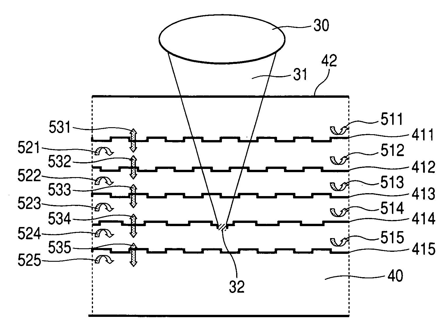
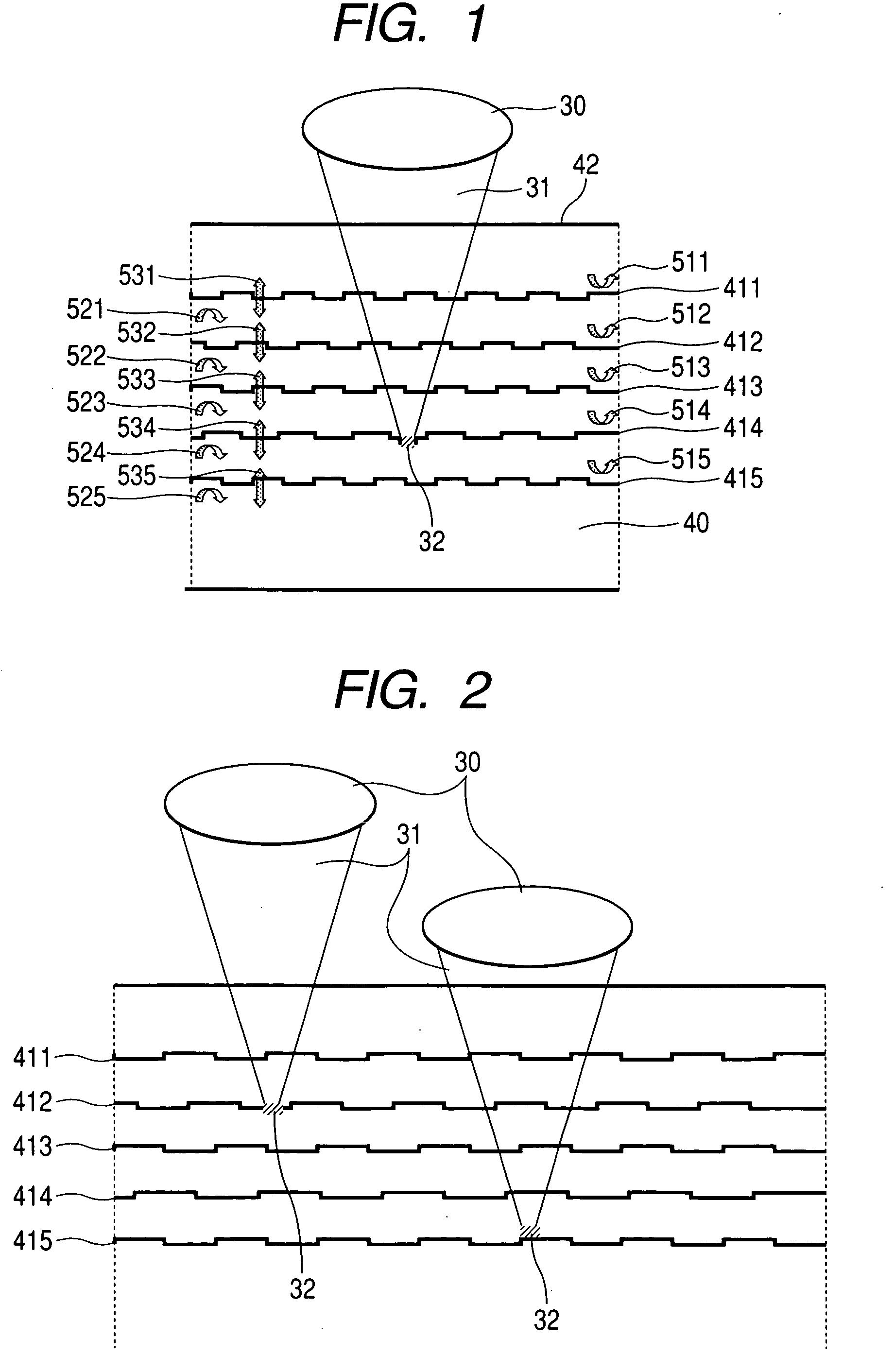
[0057]To grasp the quality of a multilayered optical recording medium, it is necessary to evaluate the effect of crosstalk on each recording layer individually. In a multilayered optical recording medium, however, crosstalk, particularly, the crosstalk caused by back reflection forms an unwanted optical spot on an untargeted layer as shown in FIG. 4. It is difficult to isolate the effect of such crosstalk in a detection instrument. This is because light reflected from the optical spot formed by the incident light and light reflected from an optical spot formed by unwanted light return to an optical head through approximately identical paths. The present embodiment provides a signal isolation method in which each of multiple layers is provided with a unique signal.
[0058]As shown in FIG. 6A, a layer identification signal area is provided in an inner radial area of a recording medium 1. In the area, different signals as shown in FIG. 6B are recorded on different layers....
Example
Fourth Embodiment
[0060]FIG. 7 shows another embodiment of an arrangement for identifying and evaluating interlayer crosstalk. In the arrangement shown in FIG. 7, plural areas in each of which a signal is recorded only on one layer are provided in a portion of an optical recording disc with none of the plural areas overlapping with another. In this case, it is important to provide a no-signal area between signal-recorded areas by taking spread of convergent light into consideration.
[0061]An advantage of this method is that, in a state in which focus has been set on a layer, the effect of crosstalk from other layers can be observed with ease. In this case, single-frequency signals need not necessarily be recorded, but, from a viewpoint of detection sensitivity, it is desirable to use a repetition signal of one type or another. In this method, too, it is possible, as in the third embodiment, to record single-frequency signals in a signal area and evaluate the effect of crosstalk withou...
PUM
 Abstract
Description
Claims
Application Information
 - R&D
- Intellectual Property
- Life Sciences
- Materials
- Tech Scout
- Unparalleled Data Quality
- Higher Quality Content
- 60% Fewer Hallucinations
Browse by: Latest US Patents, China's latest patents, Technical Efficacy Thesaurus, Application Domain, Technology Topic, Popular Technical Reports.
© 2025 PatSnap. All rights reserved.Legal|Privacy policy|Modern Slavery Act Transparency Statement|Sitemap|About US| Contact US: help@patsnap.com


