
Method and Apparatus for Shared Parameter Estimation in a Generalized Rake Receiver

a generalized rake receiver and parameter estimation technology, applied in the field of wireless communication systems, can solve the problems of severe interference of low-data-rate signals, computationally demanding estimation of rsub>d /sub>, and the user of high-data-rate signals is subject to severe interference from another high-data-rate user, so as to reduce the interference between signals

Inactive Publication Date: 2007-08-16
TELEFON AB LM ERICSSON (PUBL)
View PDF14 Cites 23 Cited by
  • Summary
  • Abstract
  • Description
  • Claims
  • Application Information

AI Technical Summary

Benefits of technology

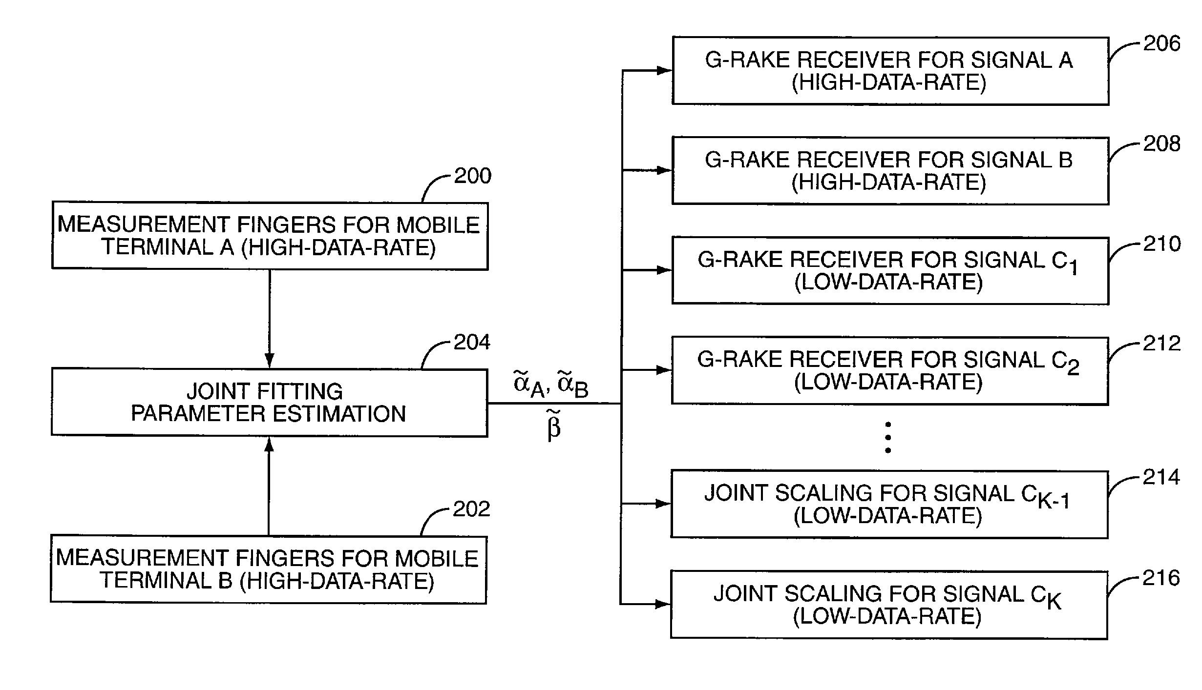
[0012] The present invention provides a method and apparatus to estimate signal impairment correlations for a plurality of signals employing a model-based, parametric technique. In one or more exemplary embodiments, the present invention comprises a method of determining received signal impairment correlations for use in generating RAKE combining weights for a plurality of G-RAKE receivers associated with one or more signals, such interference between signals is reduced.

Problems solved by technology

In this case, the low-data-rate signals are subject to severe interference from the higher-power, high-data-rate signals.
Similarly, a high-data-rate user is subject to severe interference from another high-data-rate user.
However, when there are a large number of a finger delay pairs according to the G-RAKE finger delays of the various receivers, estimating Rd becomes computationally demanding.
The computation of a consumes additional resources, such as Digital Signal Processor (DSP) computational cycles.
Accordingly, the ability to efficiently estimate the impairment covariance matrix Ru—from which combining weights may be calculated directly according to equation (1)—with sufficient accuracy and rapidity stands as a primary challenge associated with implementation of the G-RAKE receiver.

Method used


Image

  • Method and Apparatus for Shared Parameter Estimation in a Generalized Rake Receiver
  • Method and Apparatus for Shared Parameter Estimation in a Generalized Rake Receiver
  • Method and Apparatus for Shared Parameter Estimation in a Generalized Rake Receiver

Examples


Embodiment Construction

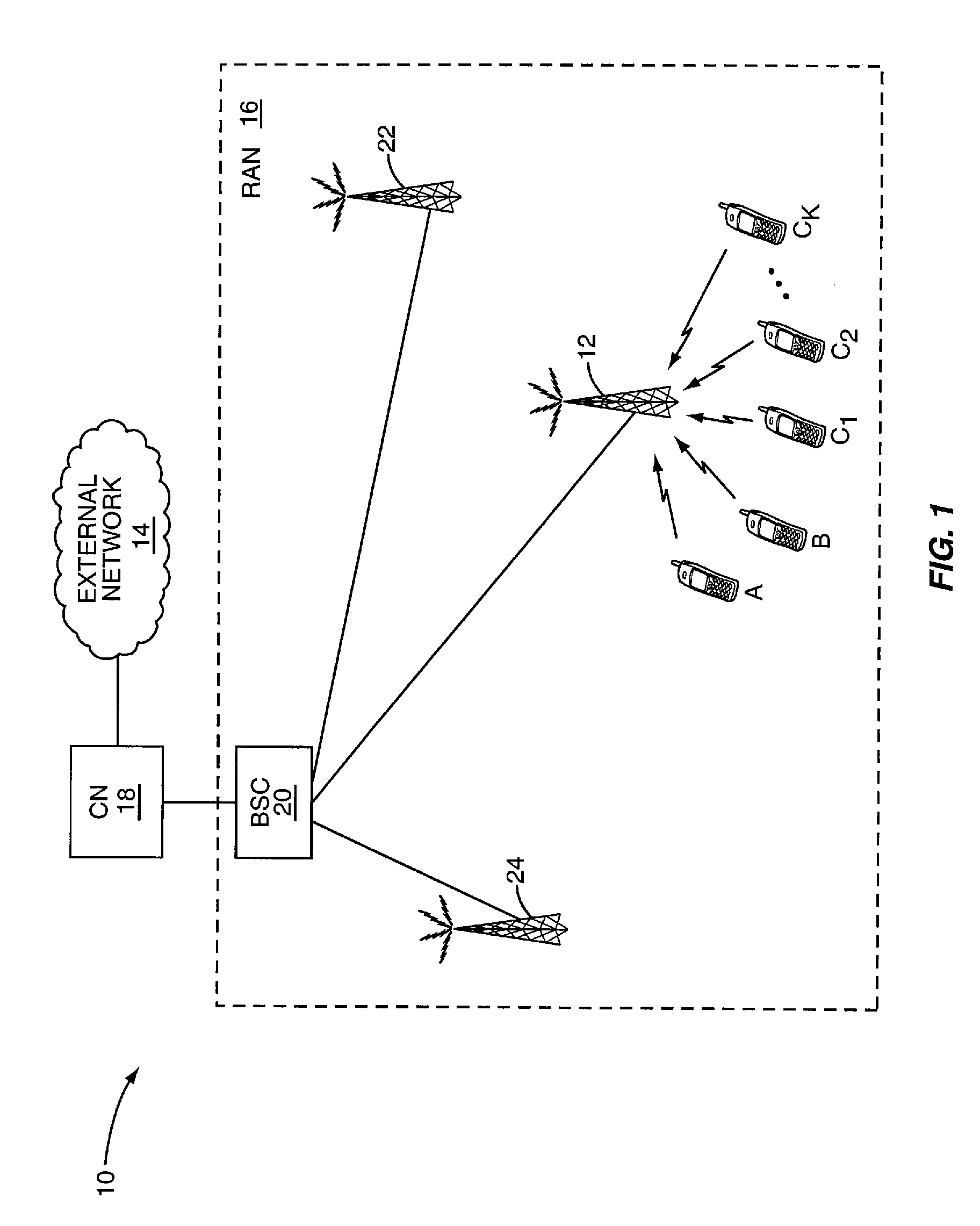
[0023]FIG. 1 illustrates an exemplary wireless communication network 10, which may be configured as a WCDMA wireless cellular network, as an IS-95 / IS-2000 wireless cellular network, or configured according to some other open or proprietary communication standard. The network 10 provides voice and data communication services to a plurality of mobile terminals A, B, C1, C2, . . . Ck operating within a radio service area known as a sector or cell. Those skilled in the art will appreciate that the terms “cell” and / or “sector” as used herein should be given broad construction and, in general, the term sector should be understood as identifying a given radio coverage area at a given carrier frequency. Thus, a given cell may have multiple overlaid radio sectors corresponding to multiple carrier frequencies.

[0024] The network 10 communicatively couples the mobile terminals A, B, C1, C2, . . . Ck to each other, to other mobile terminals in the network 10, or to one or more external networks...


PUM


Abstract

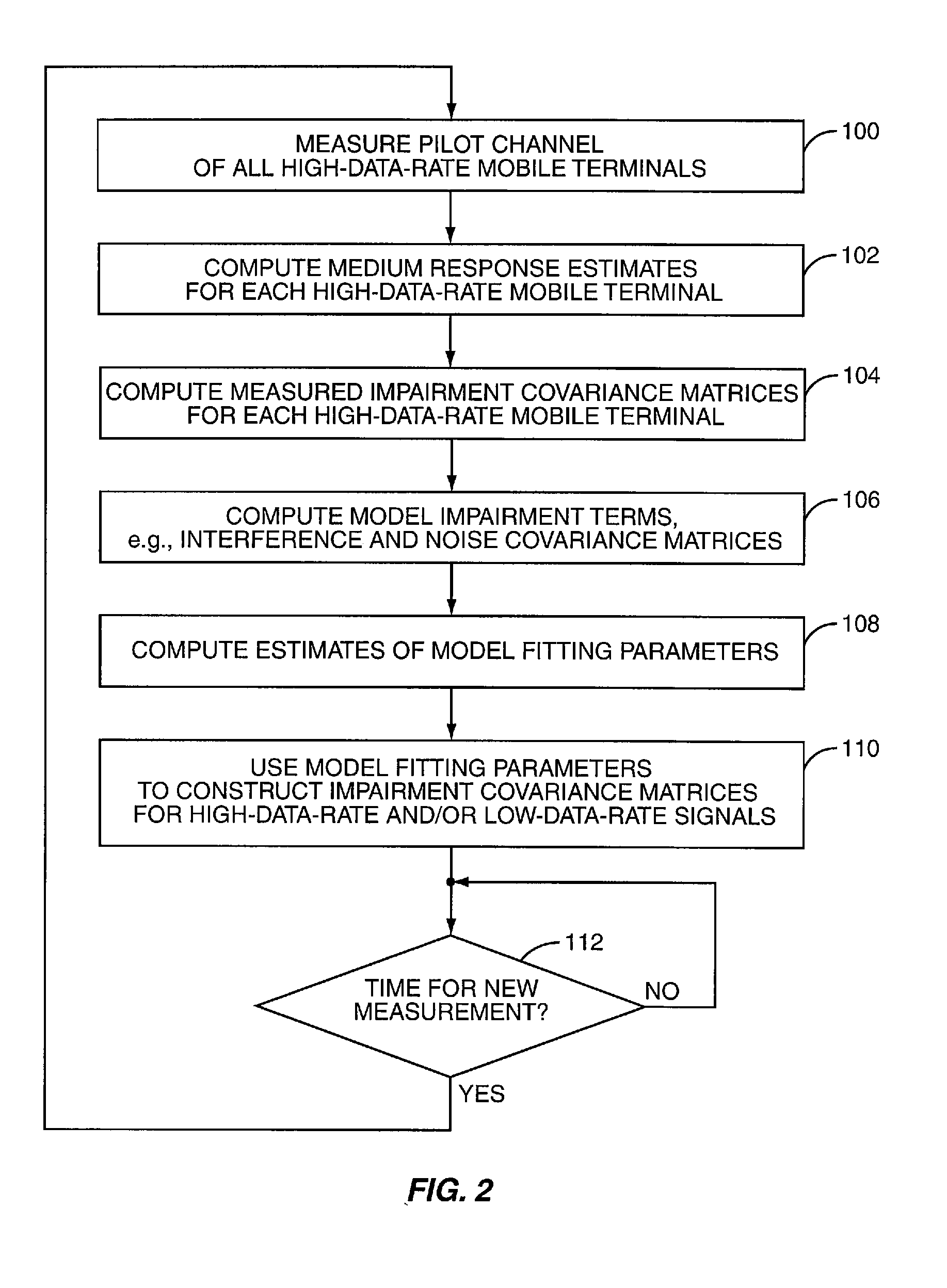
Signal impairment correlations for multiple signals in a received multipath signal are constructed by fitting parametric models associated with each high-data-rate signal in the multipath against measured impairment correlations. The estimated model fitting parameters are applied to form impairment correlation estimates for all signals. The models comprise a separate impairment covariance matrix scaled by a model fitting parameter for each high-data-rate signal and a noise covariance matrix scaled by a noise element model fitting parameter. The model fitting parameters may be estimated by a least-squares formulation and applied to form impairment correlation estimates for all signals of interest. The resulting impairment correlation estimates may be provided to G-RAKE receivers or joint scaling demodulators to demodulate the signals while suppressing interference from the high-data-rate signals.

Description

[0001] This application is a continuation-in-part of U.S. patent Ser. No. 11 / 276,069, REDUCED COMPLEXITY INTERFERENCE SUPPRESSION FOR WIRELESS COMMUNICATIONS, filed Feb. 13, 2005, which is incorporated herein by reference in its entirety. The new matter of this application claims priority to provisional application Ser. No. 60 / 825,441, filed Sep. 13, 2006.BACKGROUND OF THE INVENTION [0002] The present invention generally relates to wireless communication systems, and in particular to minimizing interference from high-data-rate users in the uplink. [0003] Wireless communication systems are widely deployed, providing voice and data communication services to mobile users. As wireless communication technology advances, mobile users may send and receive a wide variety of data—such as audio, video, images, e-mail, web browser content, and the like—in addition to traditional voice communications. Many such data transfers require much higher bandwidth than does digitally encoded voice. For ...

Claims


Application Information

Patent Timeline
Patent Type & Authority Applications(United States)
IPC IPC(8): H04B1/00H04B1/7105H04B1/712
CPCH04B1/7105H04B2201/709727H04B2201/70703H04B1/712
Inventor WANG, YI-PIN ERICCOZZO, CARMELABOTTOMLEY, GREGORY E.PETERS, GUNNAR
Owner TELEFON AB LM ERICSSON (PUBL)
Learn More