Automatic Speed Reducing Ratio-Switching Apparatus

a technology of automatic speed reduction and ratio switching, which is applied in mechanical equipment, gearing details, gearing, etc., can solve the problem that the movement speed of the screw shaft cannot be increased to a higher speed during the expansion operation, and achieve the effect of smooth transmission of torqu

Active Publication Date: 2007-08-16
SMC CORP
View PDF17 Cites 83 Cited by
  • Summary
  • Abstract
  • Description
  • Claims
  • Application Information

AI Technical Summary

Benefits of technology

[0010]A general object of the present invention is to provide an automatic speed reducing ratio-switching apparatus, which makes it po

Problems solved by technology

Therefore, the movement speed of the screw shaft cannot be increased to a higher speed durin

Method used


Image

  • Automatic Speed Reducing Ratio-Switching Apparatus
  • Automatic Speed Reducing Ratio-Switching Apparatus
  • Automatic Speed Reducing Ratio-Switching Apparatus

Examples


Embodiment Construction

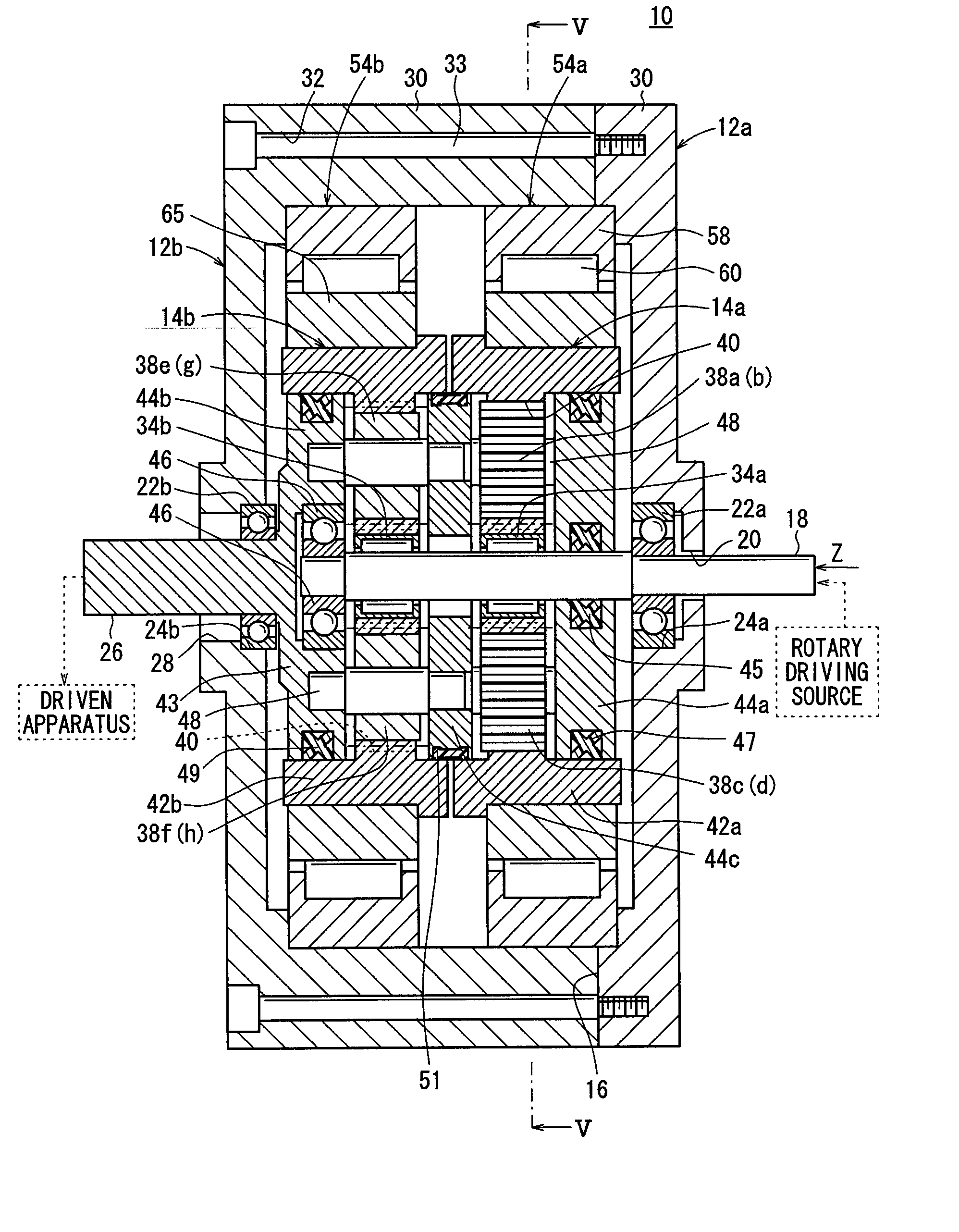
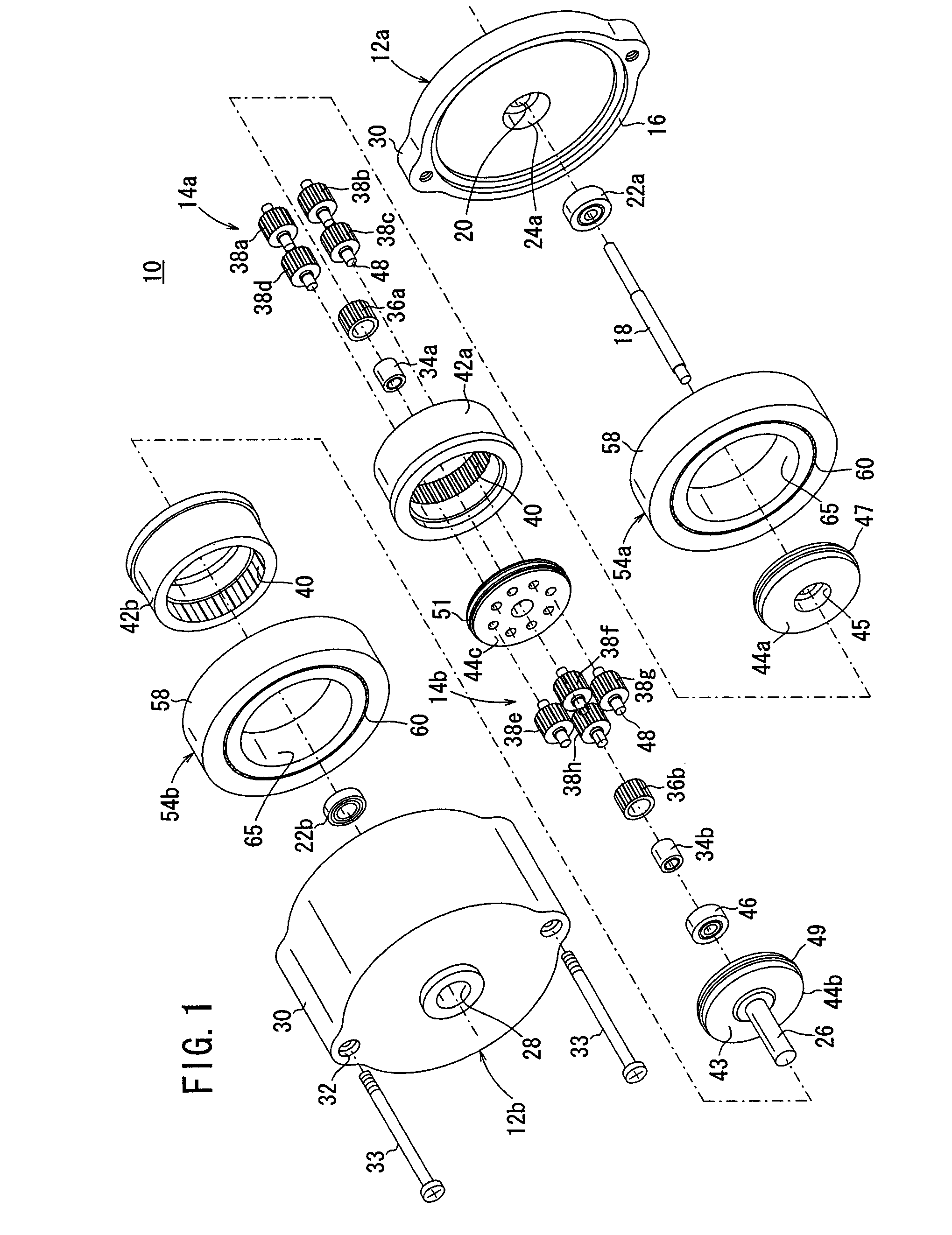
[0060]FIG. 1 shows an exploded perspective view illustrating an automatic speed reducing ratio-switching apparatus according to an embodiment of the present invention. FIG. 3 shows a longitudinal sectional view taken in the axial direction illustrating the automatic speed reducing ratio-switching apparatus.

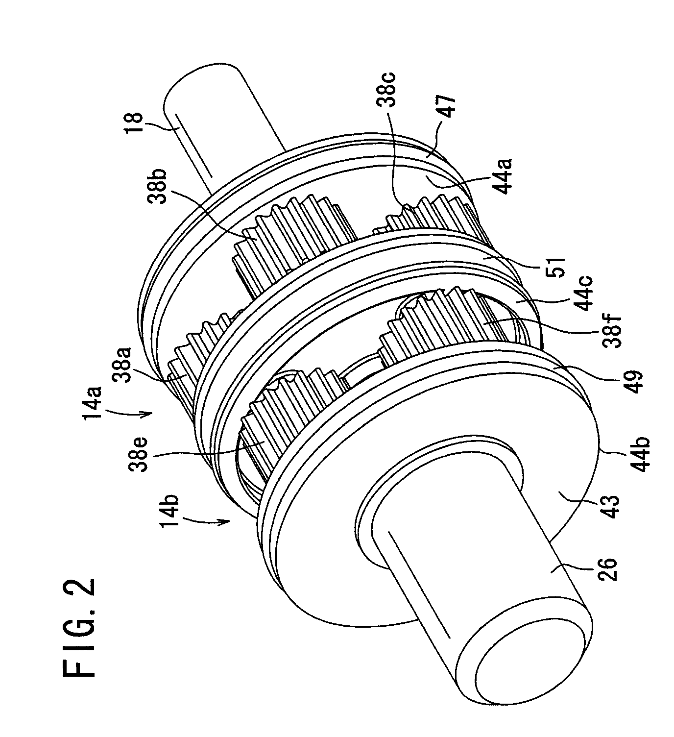
[0061]As shown in FIGS. 1 and 3, the automatic speed reducing ratio-switching apparatus 10 according to the embodiment of the present invention comprises housings 12a, 12b, which are divided into two parts, and a first planetary gear mechanism 14a and a second planetary gear mechanism 14b, which are juxtaposed in the axial direction within a chamber that is tightly sealed by the housings 12a, 12b.

[0062]The housing 12a has a disk section, which is integrally formed with a circular flange section 16. A circular hole 20, into which an input shaft 18 is inserted while leaving a portion of the input shaft 18 exposed to the outside, is formed at a central portion of the disk section. A...


PUM


Abstract

An automatic speed reducing ratio-switching apparatus comprising an input side carrier, an output side carrier, and an intermediate carrier includes first and second planetary gear mechanisms juxtaposed in the axial direction of an input shaft, first and second inner clutch members which are rotatable in one direction while locking rotation in the other direction of the input shaft, and have mutually different locking directions, first and second outer clutch members which are rotatable in one direction while locking rotation in the other direction of the input side or output side ring gear, and have mutually different locking directions, and a viscous resistance member functioning under a static frictional force to integrally rotate the input side or output side sun gear, the input side or output side planet gears, and the input side or output side ring gears respectively in an identical direction.

Description

BACKGROUND OF THE INVENTION[0001]1. Field of the Invention[0002]The present invention relates to an automatic speed reducing ratio-switching apparatus capable of automatically switching a speed reducing ratio transmitted from an output shaft, for example, to another member or apparatus through means of a planetary gear mechanism, when a load in excess of a predetermined torque is applied thereto. The present invention can be applied and utilized in a variety of extensive fields, to be described later on.[0003]2. Description of the Related Art[0004]A speed reducing ratio-switching mechanism has been hitherto applied, for example, to machine systems such as construction machines. In such machine systems, an electric cylinder is used as an actuator in an expansion / contraction operation system, for driving a link mechanism.[0005]In such an electric cylinder, a rotary shaft is connected to an input portion of an electric motor housed within a casing, and a screw shaft is arranged in conn...

Claims


Application Information

Patent Timeline
IPC IPC(8): F16H3/44
CPCF16H3/66F16H3/005F16H1/28F16H3/00F16H3/44
Inventor NAGAI, SHIGEKAZUMASUI, RYUICHI
Owner SMC CORP
Why Eureka
Try Eureka