
Optical disc device and method of controlling the same

a technology of optical discs and optical discs, which is applied in the field of optical disc devices and a method of controlling optical disc devices, can solve the problems of inconvenient inserting/removing discs into/from slim optical disc devices, the upper limit of the thickness of the optical disc devices used for portable electric devices such as notebook computers, and the inability to meet the needs of portable electric apparatuses. , to achieve the effect of compact structure, fewer components and stable protection from vibration and impacts

Inactive Publication Date: 2007-08-16
TOSHIBA SAMSUNG STORAGE TECH KOREA CORP
View PDF3 Cites 17 Cited by
  • Summary
  • Abstract
  • Description
  • Claims
  • Application Information

AI Technical Summary

Benefits of technology

[0011]The present invention provides an optical disc device having a compact structure requiring fewer components and a method of controlling the optical device. The optical disc device can be stably protected from vibrations and impacts, and discs having various diameters can be automatically inserted into and removed from the optical disc device by an automatic slot-in method. Furthermore, the thickness of the optical disc device can be reduced below a current thickness limit.

Problems solved by technology

However, conventional optical disc devices using optical discs are not suitable for portable electric apparatuses since the optical disc devices are too large and thick for use in portable electric apparatuses.
Although slim optical disc devices can be used for the portable electric apparatuses, it is inconvenient to insert / remove a disc into / from the slim optical disc device.
Moreover, there can be an upper limit to the thickness of an optical disc device used for a portable electric apparatus such as a notebook computer.

Method used


Image

  • Optical disc device and method of controlling the same
  • Optical disc device and method of controlling the same
  • Optical disc device and method of controlling the same

Examples


Embodiment Construction

[0065]The present invention will now be described more fully with reference to the accompanying drawings, in which exemplary embodiments of the invention are shown. The invention may, however, be embodied in many different forms and should not be construed as being limited to the embodiments set forth herein; rather, these embodiments are provided so that this disclosure will be thorough and complete, and will fully convey the concept of the invention to those skilled in the art. In the drawings, like reference numerals denote like elements.

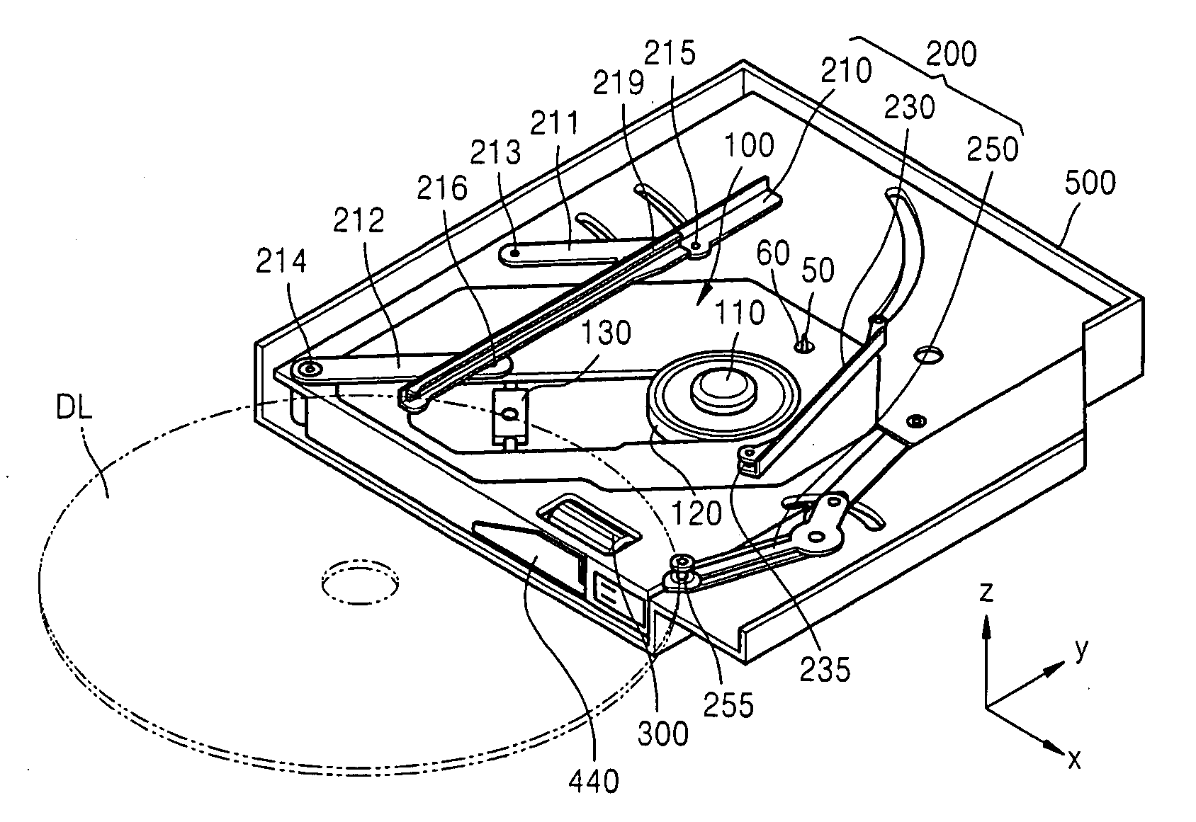
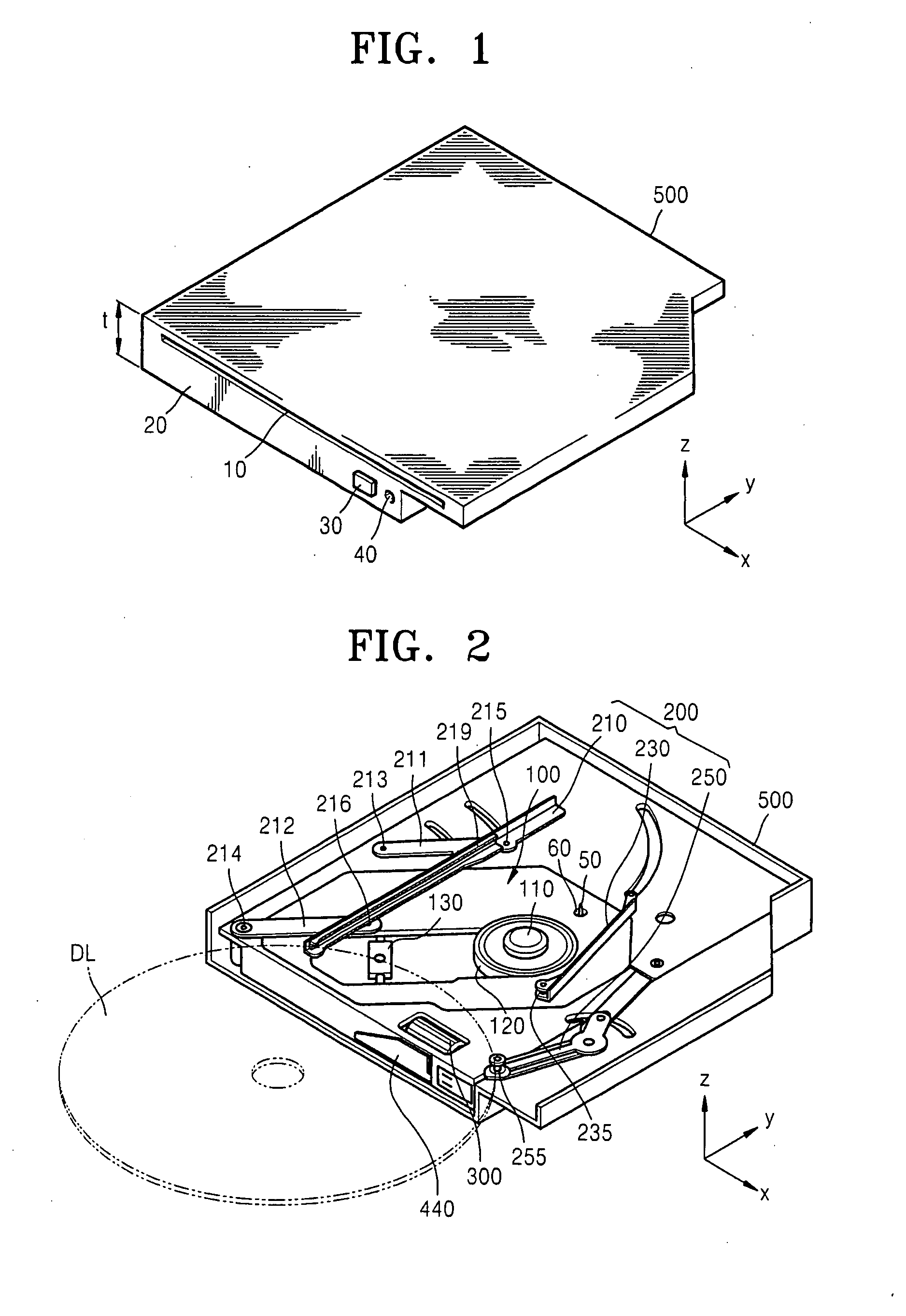
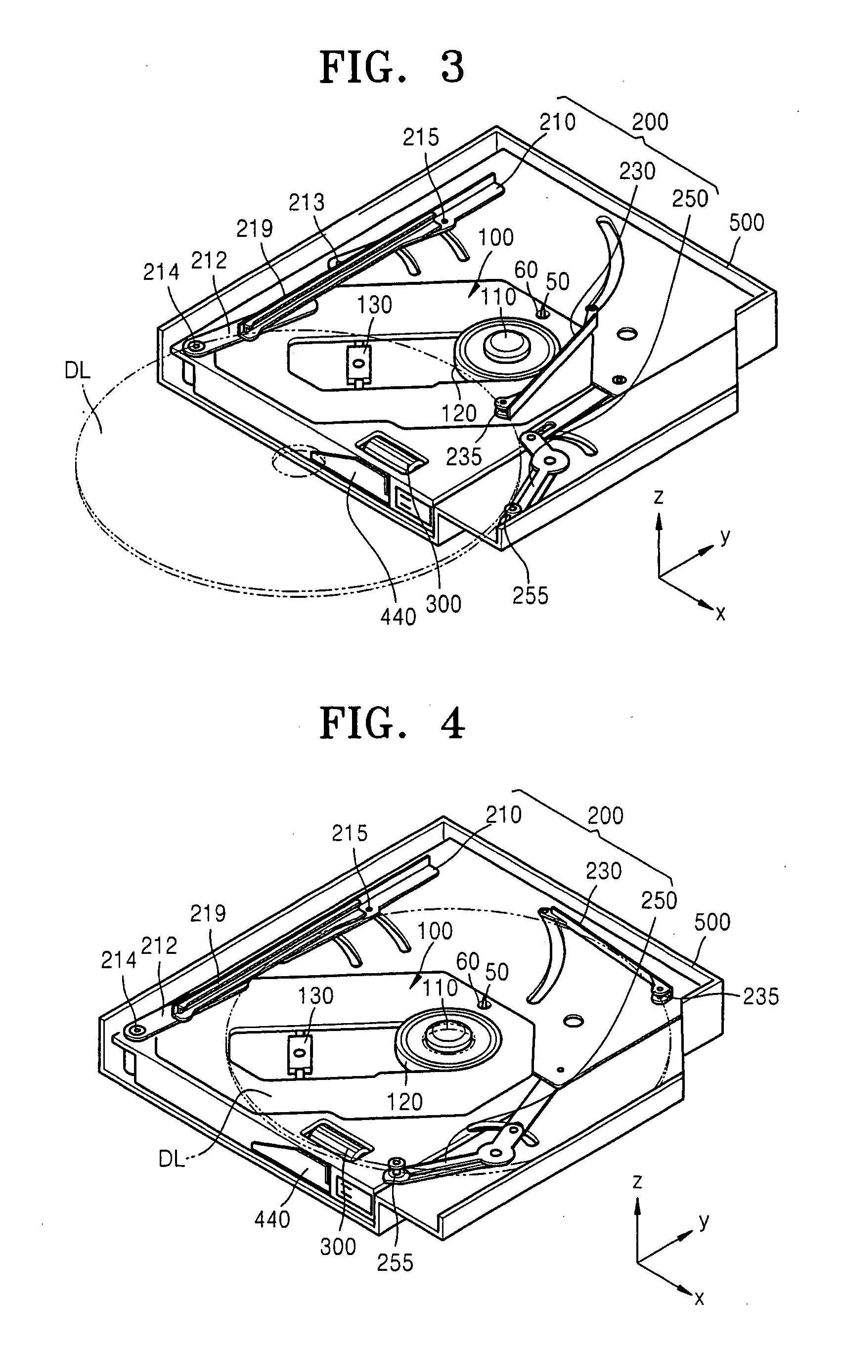
[0066]FIG. 1 is a perspective view illustrating an optical disc device according to an embodiment of the present invention. A bezel 20 is formed on the front of the optical disc device. The bezel 20 includes a slot 10 through which a disc is inserted and ejected. When an eject button 30 formed on the bezel 20 is pressed, a disc loaded in the optical disc device is removed from the optical disc device. A display lamp 40 is used to display the oper...


PUM

PropertyMeasurementUnit
thicknessaaaaaaaaaa
diameteraaaaaaaaaa
diameteraaaaaaaaaa

Abstract

The optical disc device includes a main unit rotating a turntable when a disc is coupled to the turntable and including an optical pick-up unit writing / reading data to / from the disc; a lever member guiding the disc to load the disc to a position at which a center of the disc is aligned with a center of the turntable and reversely guiding the disc to unload the disc, the lever member being capable of loading / unloading discs having various diameters; and a driving unit actuating the lever member. The method of controlling the optical disc device includes detecting a diameter of a disc; loading the disc to a position at which a center of the disc is aligned with the center of the turntable; coupling the disc to the turntable; and moving the lever member away from the disc to allow writing / reading data to / from the disc to be performed.

Description

CROSS-REFERENCE TO RELATED APPLICATIONS[0001]This application claims the benefit of Korean Patent Application No. 10-2006-0015245, filed on Feb. 16, 2006, and Korean Patent Application No. 10-2007-0003409, filed on Jan. 11, 2007, in the Korean Intellectual Property Office, the disclosures of which are incorporated herein in their entirety by reference.BACKGROUND OF THE INVENTION[0002]1. Field of the Invention[0003]The present invention relates to an optical disc device and a method of controlling the optical disc device, and more particularly, to an optical disc device having a slot for receiving / removing an optical disc and a method of controlling the optical disc device.[0004]2. Description of the Related Art[0005]Examples of data storage mediums include magnetic discs such as floppy discs and hard discs, magnetic tapes, semiconductor memory chips such as read-only memory (ROM) and random-access memory (RAM), and optical discs.[0006]The use of optical discs (hereinafter, also refe...

Claims


Application Information

Patent Timeline
Patent Type & Authority Applications(United States)
IPC IPC(8): G11B17/04
CPCG11B17/0515
Inventor AHN, CHEOL-WOONGYOON, JAE-HYUNCHOI, UN-JINYEOM, JEONG-HUNLEE, MYONG-CHUN
Owner TOSHIBA SAMSUNG STORAGE TECH KOREA CORP
Learn More