
Heel protector

a protector and heel technology, applied in the field of heel protectors, can solve the problems of inability to prevent the formation of calluses or blisters caused by friction cannot be prevented, and the formation of calluses or blisters cannot be prevented, so as to achieve the effect of restricting the generated friction and preventing the formation of calluses and blisters

Inactive Publication Date: 2007-08-23
JOEUN PROTECH
View PDF3 Cites 15 Cited by
  • Summary
  • Abstract
  • Description
  • Claims
  • Application Information

AI Technical Summary

Benefits of technology

[0006] The present invention is disclosed to solve the aforementioned drawbacks and it is an object of the present invention to provide a heel protector configured to maximally restrict friction generated between a heel and a shoe from occurring while walking, thereby preventing formation of calluses and blisters.
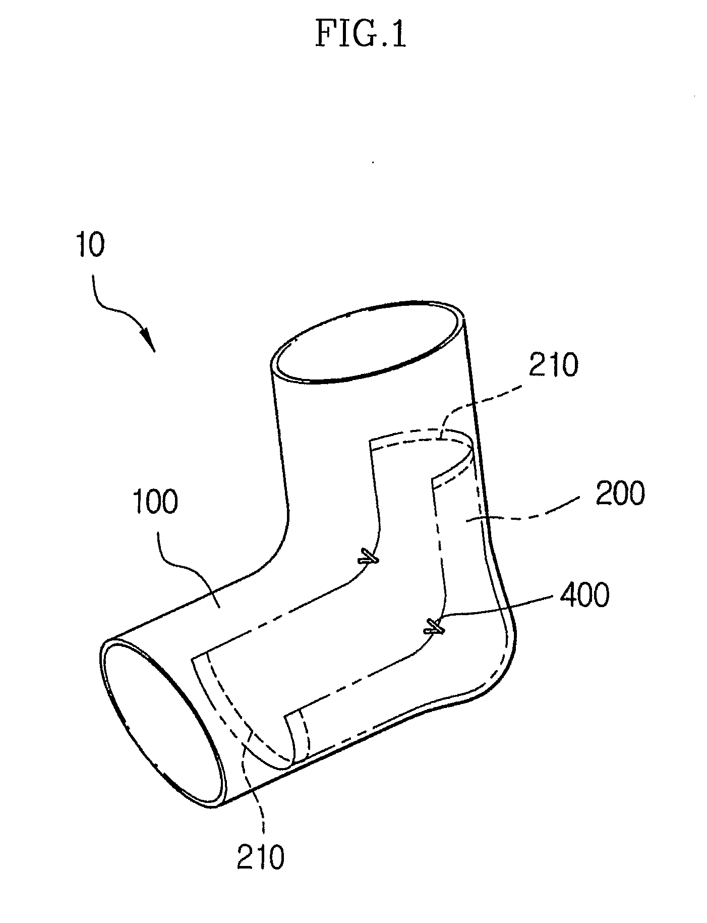
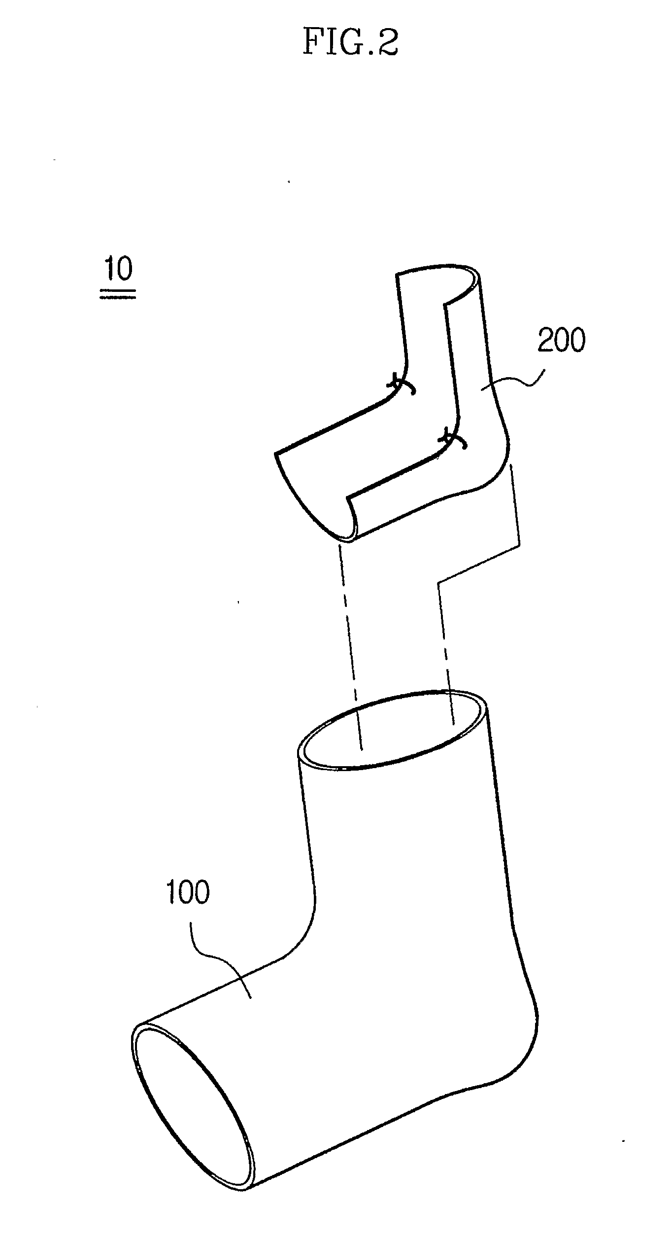
[0007] In accordance with a preferred embodiment of the present invention, the heel protector includes a body member made of a flexible fabric material for being worn on the feet and an inner pad member coupled to an inside of the body member for accommodation to an area where a heel is located when the heel protector is worn, wherein both distal ends of longitudinal direction of the inner pad member are coupled to the body member, and two areas of the inner pad member accommodated to both lateral sections of the heel are coupled to the body member, such that the inner pad member can relatively slide in relation to the body member when the heel protector is worn.

Problems solved by technology

However, formation of calluses or blisters caused by friction cannot be prevented.
Thus, it cannot prevent formation of calluses or blisters caused by friction.
Therefore, in this utility model, there is a drawback in that calluses and blisters caused by friction cannot be prevented from being formed.

Method used


Image

  • Heel protector
  • Heel protector
  • Heel protector

Examples


Embodiment Construction

[0022] The preferred embodiments of the present invention will now be described in detail with reference to the annexed drawings, where the present embodiments are not limiting the scope of the present invention but are given only as an illustrative purpose, and throughout the drawings, like reference numerals are used for designation of like or equivalent parts or portions for simplicity of illustration and explanation.

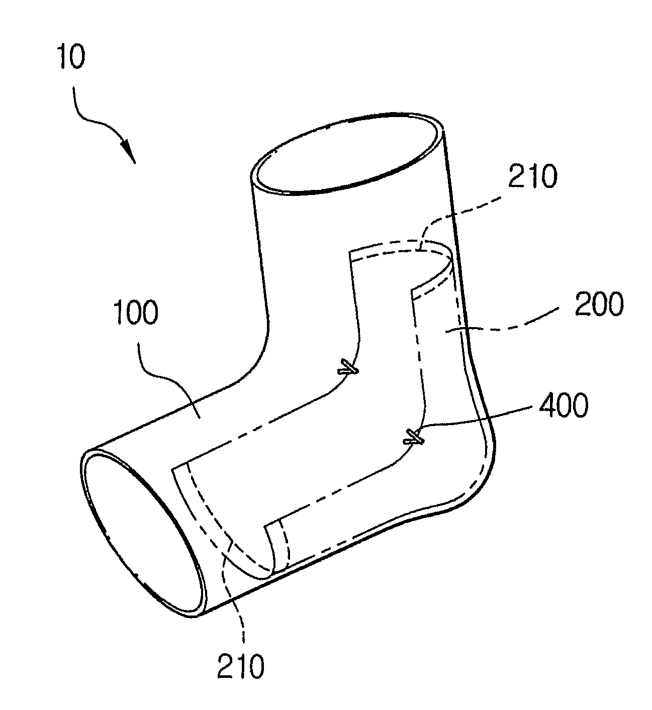
[0023] Referring to FIGS. 1 and 2, a heel protector (10) according to the present invention includes a body member (100) and an inner pad member (200).

[0024] The body member (100) has a cylindrically bent “L” shape and is made of a flexible fabric material. In other words, the body member (100) has a shape of a sock cut out at a front section thereof. A user may wear the body member (100) just like a sock or may insert the body member (100) inside a sock to encompass the heel of the user.

[0025] It should be appreciated that although a so-called ankle protector hav...


PUM


Abstract

Disclosed herein is a heel protector including a body member made of a flexible fabric material for being worn on the feet and an inner pad member coupled to an inside of the body member for accommodation to an area where a heel is located when the heel protector is worn. Both distal ends of a longitudinal direction of the inner pad member are coupled to the body member, and two areas of the inner pad member accommodated to both lateral sections of the heel are coupled to the body member, such that the inner pad member can relatively slide in relation to the body member when the heel protector is worn. Friction generated on the heels while walking can be subdued by the inner pad member to thereby prevent formation of calluses or blisters, and manufacturing process can be simplified to reduce the manufacturing cost.

Description

FIELD OF THE INVENTION [0001] The present invention relates to a heel protector and, more particularly, to a heel protector adapted to maximally prevent friction between a user's heel and shoes, and to prevent formation of calluses and blisters on the heel caused by the friction. BACKGROUND OF THE INVENTION [0002] One of the known arts for maintaining healthy feet is shown in FIG. 11, in which Japanese Utility Model No. 3032803 entitled, “Dryness Preventing Socks,” is described. In this Utility Model, the overall border of an inner pad member (520a) attached to a heel is connected to a sock (510a) by stitching (530a) in the shape of the heel. As a result, the overall inner pad member (520a) is secured to the sock and the only effect is to prevent dryness of the heels. [0003] In Japanese Laid-open Patent Application No. 2002-235203, entitled “Dryness Preventing Socks” and illustrated in FIG. 12, formation of calluses caused by dryness of a heel or sole can be prevented by attaching a...

Claims


Application Information

Patent Timeline
Patent Type & Authority Applications(United States)
IPC IPC(8): A41B11/00A41B11/08
CPCA41B11/00
Inventor YOON, MIN SEOK
Owner JOEUN PROTECH
Learn More